

Construction description antenna trap
An antenna trap is used in multiband antennas. The antenna trap blocks a certain frequency. This shields part of the antenna for higher frequencies where a shorter antenna is needed. The entire antenna participates for the lower frequencies on which the trap does not block. This can be applied in dipole antennas where each leg of the antenna needs a trap, but also in end-fed antennas where only one trap is needed.
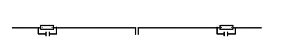
Dipole antenna with traps
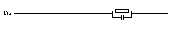
End fed antenna with traps
Resonance frequency of the antenna trap
A trap is a parallel circuit of a capacitor and an inductor. The frequency at which the antenna trap has a high resistance (so it blocks) depends on the coil and capacitor. The resonance frequency is determined by the formula below.

I choose to use an easy program that does the math for you.
Download link to Mini Ringker Rechner: Click here!!!
The installation is in German but in the program the language can be changed to English.
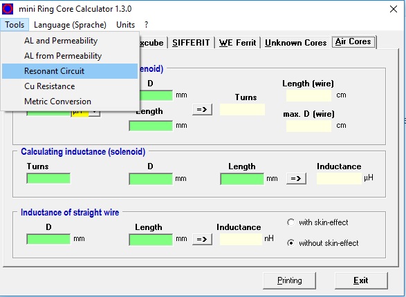
First we will determine the value of the coil and capacitor. In the program, choose: Tools –> Resonant Circuit. HF Kits supplies two high voltage capacitors of 100 pF in the kit. With this, three combinations can be made on the antenna trap circuit board. Namely 50 pF, 100 pF and 200 pF. How to do this exactly is discussed below. For the high frequencies (10 to 15 meters) I would personally choose 50 pF, for 17 to 30 meters 100 pF and for 40 to 80 meters 200 pF. In this example we make a trap for the 10 meter band so we choose as capacitor value 50 pF.
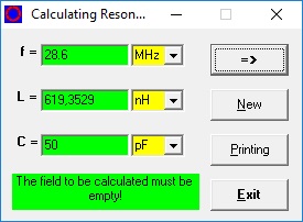
I entered 50 pF as capacitor value and a frequency of 28.6 MHz. The antenna trap is pretty wideband so the frequency doesn’t come close to a few kilohertz. If I then click on the arrow, the value of the coil is calculated. In this case 619.35 nH. So now we know we can make a trap with a capacitor of 50 pF and a coil of 619.35 nH.
Soldering capacitors
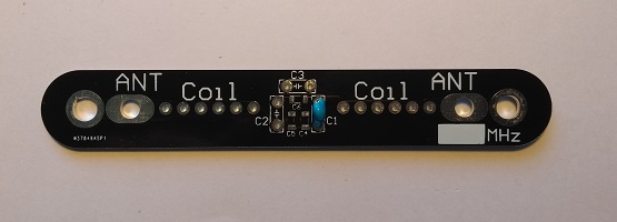
On the PCB is space for 3 capacitors C1, C2 and C3. (and possibly for SMD capacitors C4, C5 and C6). The PCB is designed in such a way that it is possible to use one capacitor, to connect two capacitors in parallel or to connect two capacitors in series.
50 pF –> Two capacitors in series, solder them in C2 and C3.
100 pF –> Solder one capacitor in C1
200 pF –> Solder two capacitors in C1 and C2 and a wire bridge in C3.
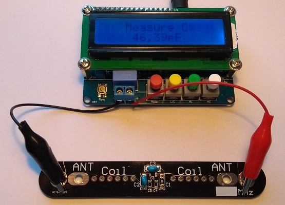
After soldering the capacitors I check the value. The capacitors have a 10% tolerance. In this case the value is also a bit lower, 46.39 pF.
Because the capacitors have a different value in practice, the value of the coil must be determined again! result –> 667,55 nH

Determine the number of windings of the coil
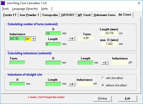
Now return to the main program and choose the tab “Air Cores”. Now enter the inductance of the coil as we calculated earlier in “Resonant Circuit” calculator. Next we fill in the diameter of the coil, which in our case is 19 mm. Then I experimentally determine the length of the coil, I choose about 1 mm per winding, so this is a matter of trial and error. I now calculate 4,99 ( so 5 ) windings with a coil length of 5 mm. We use winding wire of 0.75 mm so this should give a minimum coil length of (5 x 0.75 mm) 3.75 mm. So there is still some space to slide the coil in and out which is necessary to bring the trap exactly to the right resonance frequency. This will be addressed later when tuning the trap.
Mounting the coil
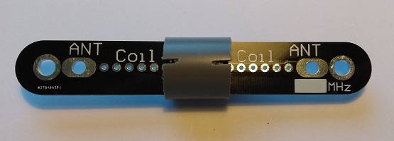
Now the capacitors are soldered, the coil can be started. The base of the coil is in our case a PVC tube in which the PCB fits exactly. Saw in the PVC pipe on two sides, so it forms an easy start and end point of the coil.
Solder the enameled copper wire as shown in the picture below. Make sure the insulation is removed properly otherwise strange phenomena will occur, this can be done with a sharp knife or sandpaper.
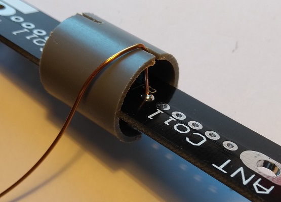
Then wind the coil as shown in the picture below (number of windings is not the same as in the example)
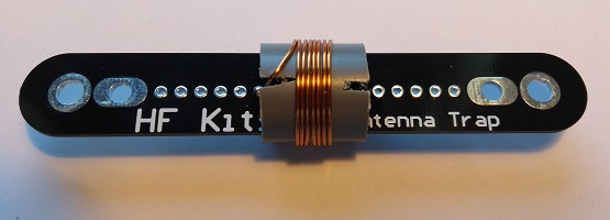
Solder the other end of the coil to the PCB. In the picture above, 7.5 windings have been chosen (I think for the 15 meter band), so it is also possible to make half windings, then you solder the end to the other side of the PCB.
Tuning the antenna trap
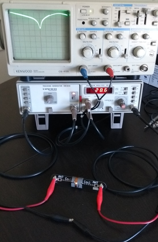
This requires a grid-dipper or spectrum analyzer. The picture below shows the pass-through characteristic of the trap. Bringing the windings of the coil closer or further apart changes the resonance frequency. Now put the trap exactly on the desired frequency, 28.6 MHz in this case.
Finishing
Now that the trap has been brought to the right resonance frequency, it is advisable to fix the coil to prevent it from slipping. I do this with some quick drying plastic spray. PVC glue is also a good alternative. After the coil is fixed, the resonance frequency is checked one more time, after which the whole can be finished with the supplied heat shrink tube. Pay attention not to heat the entire trap with the heatshrink tubing, this can deform the PVC and cause the resonance frequency to change.
Mounting the traps in the antenna
There are roughly three ways to mount the trap.
- Insert the antenna wire through the outer hole, then solder to the inner mounting point. This is a suitable way for short antennas that are not set up permanently. This way of mounting is by far the easiest because no loops, cable clips and other attributes are needed. I use this for my short end fed antennas that I use vertically in the field. Choose in this case for: Antenna trap kit, ideal for wire antennas
- Solder the antenna wire into suitable cable eyes M4 or M5 and finish with a piece of heat shrink tubing. Secure the cable lug to the outer fixing holes of the trap using M4 x 10 mm stainless steel bolts. This is a suitable way for medium sized antennas.
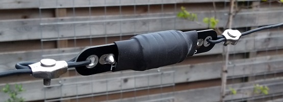
- By far the most solid way of mounting is as follows: Make a loop of wire through the outer mounting hole of the trap by means of a stainless steel cable clamp. Use stainless steel cable thimble to prevent the wire from being damaged (missing on the picture below). Solder the antenna to a suitable wire eye (M4) and finish with a piece of heat shrink tubing. Secure the cable lug to the inner fixing hole of the trap using a stainless steel M4 x 10 mm bolt. In this case, please choose: Antenna Trap Kit including cable lug and cable clamps
Example 1: multiband dipole antenna for the 10 and 20 meter band using antenna traps
Start by making two traps that are resonant at the highest frequency. That’s the 10 meter band in this example. If you make the trap’s so that the resonance frequency is at 28.6 MHz, then signals of this frequency will be blocked. Now start making a standard dipole antenna for the 10 meter band. So a feed point (preferably a 1:1 BalUn) and two pieces of antenna wire of about 2.5 meters ( 300 / 28.5 * 0.95 / 4 = 2.5 mtr). Start with a bit more length (2.8 meters) so you can still cut something. Once you have the antenna in resonance for the 10 meter band, the traps can be placed at either end. Now add the other two pieces of antenna wire for the 20 meter section. In our example also about 2.5 meters per side. Now cut the two ends to length so that the antenna is in resonance on the 20 meter band. It is also possible to apply this trick a few more times to add a few more bands to the antenna.
Example 2: multiband end-fed antenna for the 40 and 60 meter band using an antenna trap
Start by making one trap resonant at the highest frequency. That’s the 40 meter band in this example. If you make the trap so that the resonance frequency is at 7.1 MHz, then signals of this frequency will be blocked. Now start making a standard end fed antenna for the 40 meter band. So a feedpoint (1:49 impedance transformer) and a piece of antenna wire of about 20 meters ( 300 / 7,1 * 0,95 / 2 = 20 mtr). Start with some more length (21 meters) so there is still something to cut. Once you have the antenna in resonance on the 40 meter band, the trap can be placed at the end. Now add the remaining piece of antenna wire for the 60 meter section. In our example about 7 meters. Now cut the end to length so that the antenna is in resonance on the 60 meter band. It is also possible to apply this trick a few more times. This makes it possible to add more bands.