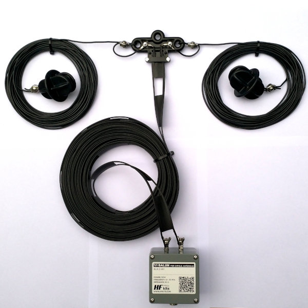
Instructions ZS6BKW, G5RV (junior/mini) Includes 1:1 balun
A ZS6BKW or G5RV is a dipole antenna fed with a certain length of ladder line. By choosing the length of the dipole antenna and ladder line favorably, the antenna can be used on various amateur bands. Most bands can be worked without an antenna tuner. The first concept of this antenna was conceived by G5RV and later improved by ZS6BKW using computer calculations. There is also a shortened G5RV antenna, this one is called the G5RV junior.
In the case of the ZS6BKW, usually the 6, 10, 12, 17, 20, 40 meter band can be worked without a tuner, for 80 meters a simple tuner is sufficient. For 15, 30 and 60 meters, this antenna is unsuitable.
In the case of the G5RV, a tuner is usually required. The 12, 15, 20, 40 and 80 meter bands can be matched with a simple tuner. On 80 meters, the SWR is slightly better compared to the ZS6BKW. For 6, 10, 17, 30 and 60 meters, this antenna is unsuitable.
The G5RV junior can usually be used without a tuner on the following bands: 10, 20 and 40 meters. For 12, 17, 15 meters, a simple tuner will suffice. For 30, 60 and 80 meters, this antenna is unsuitable.
The G5RV mini can usually be used without a tuner on the following bands: 6, 10 and 20 meters. For 12, 15, 17, 30, 40, 60 and 80 meters, this antenna is unsuitable.
The construction of the antenna is relatively simple. A dipole antenna with a piece of ladder line, then a transition to coaxial cable by means of a common mode choke (BalUn). If a transition is made from coaxial cable to “ladder line” (chicken ladder) or “open line” it is always recommended to use a “BalUn”. BalUn means: Balanced to Unbalanced. This allows us to connect an unbalanced power system (coaxial cable) to a balanced antenna system (e.g., dipole antenna). The main reason for using a BalUn is to ensure that the coaxial cable does not become part of the antenna system and therefore also radiate. This has all sorts of nasty effects, think of: interference, EMI, RFI disrupted radiation pattern of the antenna, restless noise level. The coaxial cable shield will not only radiate when transmitting but the shield will also acts as a receiving antenna.
There are many amateurs who look exclusively at the SWR of the antenna system. You may find that the SWR is more favorable without using a BalUn. If this is the case then you can assume that the coaxial cable also participates as an antenna with previously mentioned disadvantages as a result. So don’t stare at only the SWR of an antenna.
A ferrite toroidal core is used which attenuates common mode currents. The main characteristic of a good BalUn is maximum common mode current reduction and minimal loss of the differential current. There is a lot of information on the Internet and even in literature about making a BalUn, but unfortunately there are also a lot of bad designs that hardly work. This design is one that has proven to work very good! We will begin by making the BalUn for the ZS6BKW or G5RV antenna.
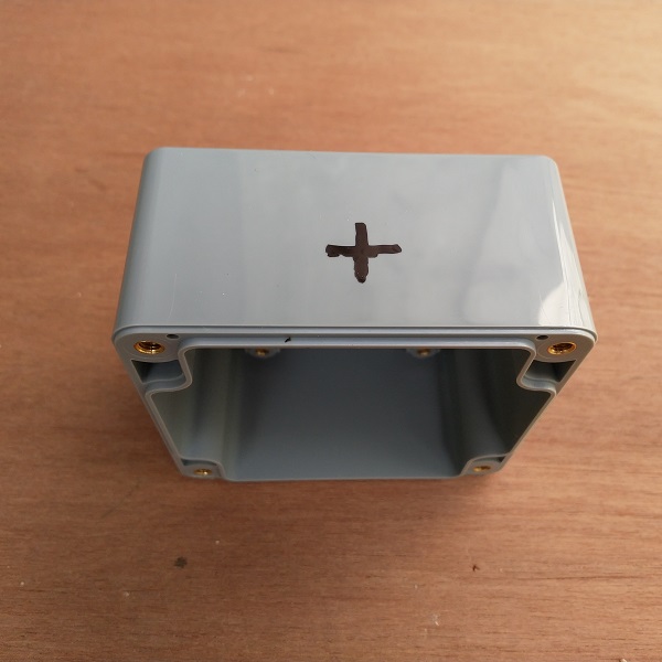
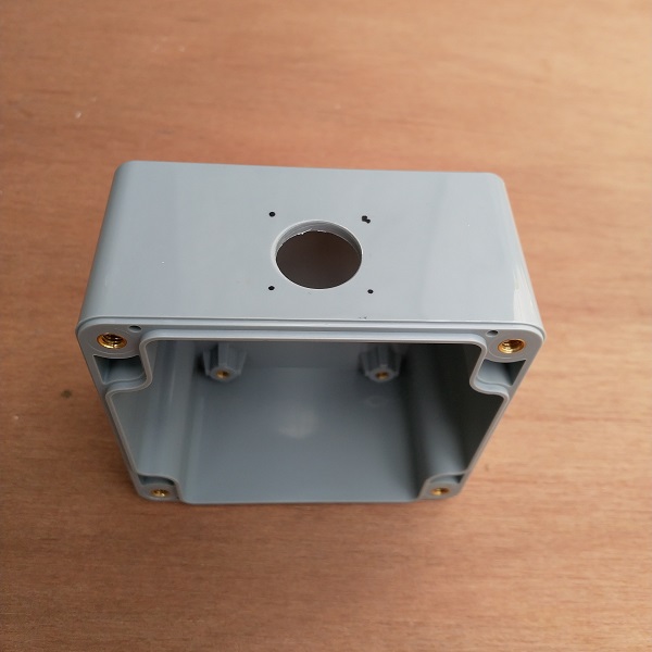
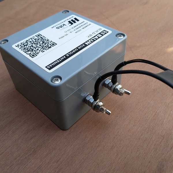
1:1 BalUn housing for ladder line
We start by marking and drilling the hole for the coax connector. The diameter of this hole should be 16 mm. This is a large hole and therefore it is easiest to create it with a ‘sheet step drill’. (If you have never heard of that, Google is your friend for looking up what you need)
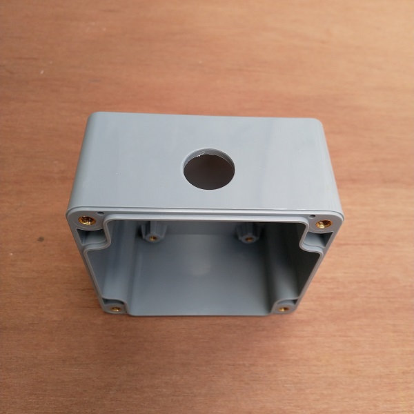
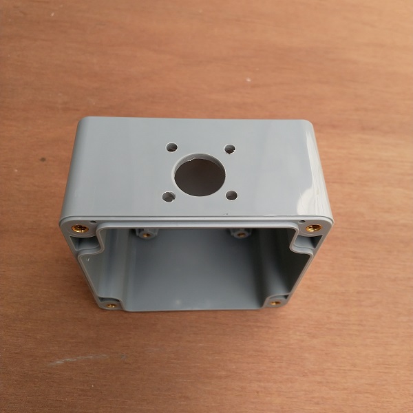
After drilling the 16 mm hole, I placed the chassis part into the hole, to determine the location of the fixing holes. I picked a chassis part where I fix the part with 4 screws, but 2 screws could also work. Drill the holes with a 3.5 mm drill bit.
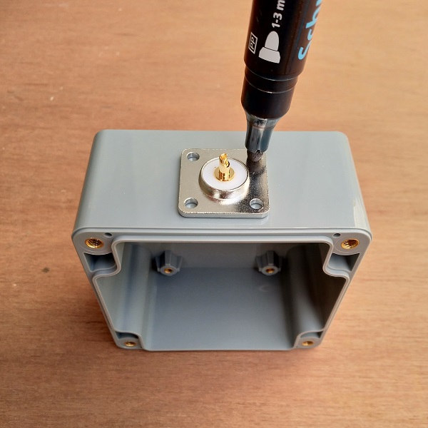
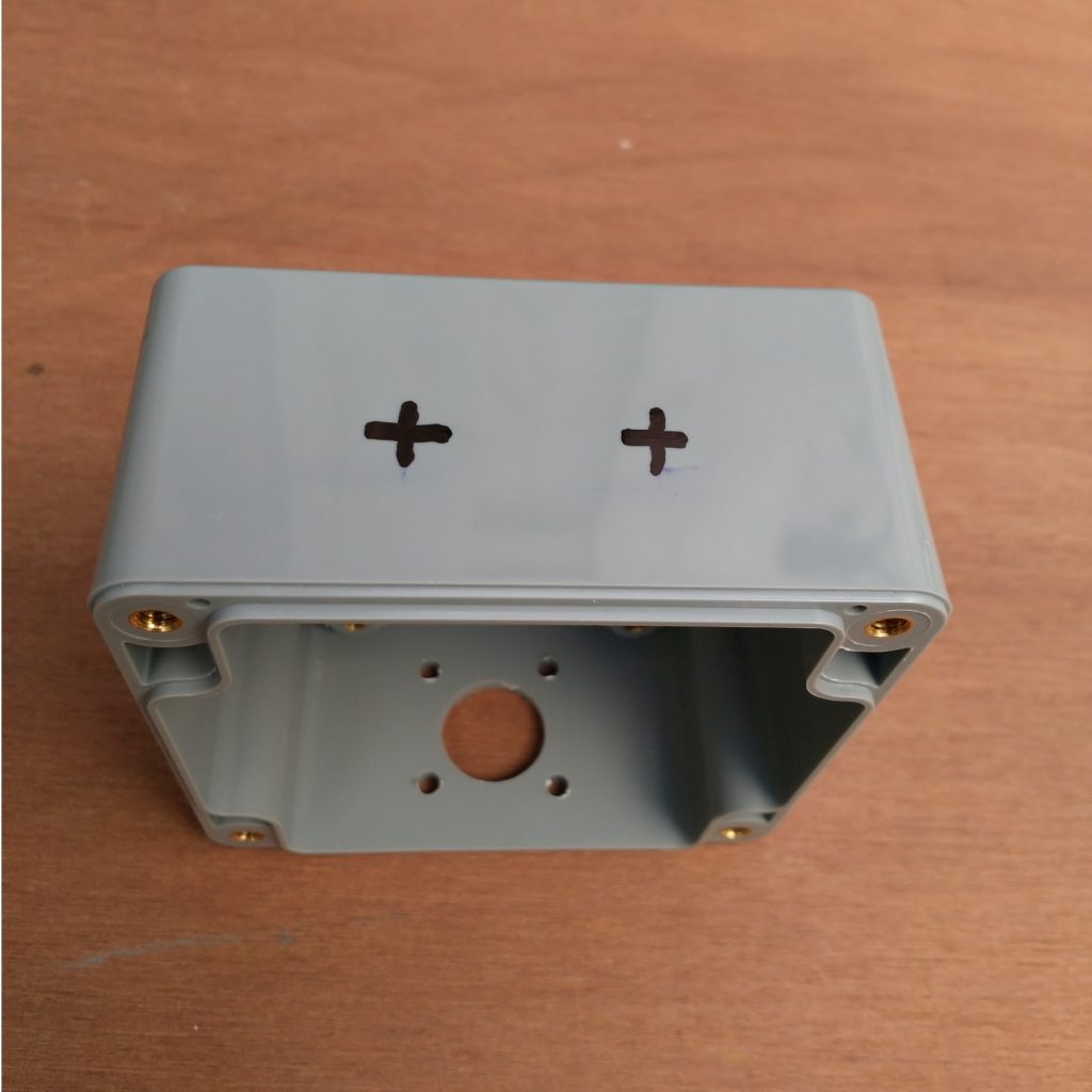
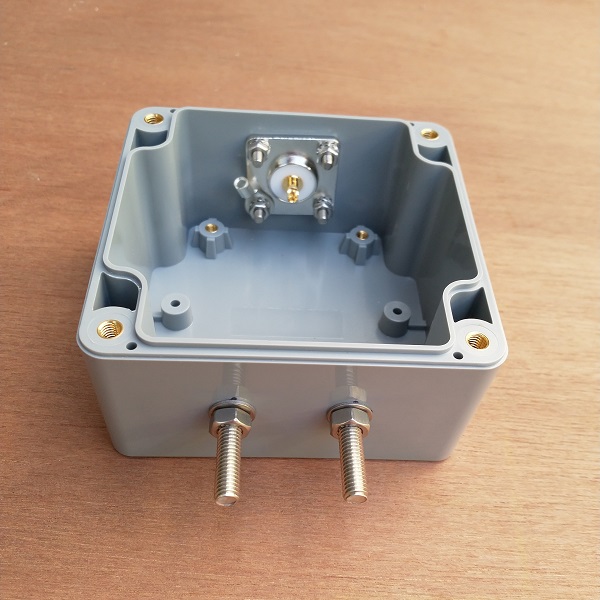
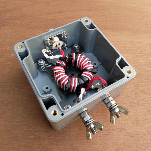
Next, we proceed to mark off and drill the holes for the ladder line connection. Drill the holes for the connections with a 5mm drill bit. The place where the holes are drilled is to your own liking.
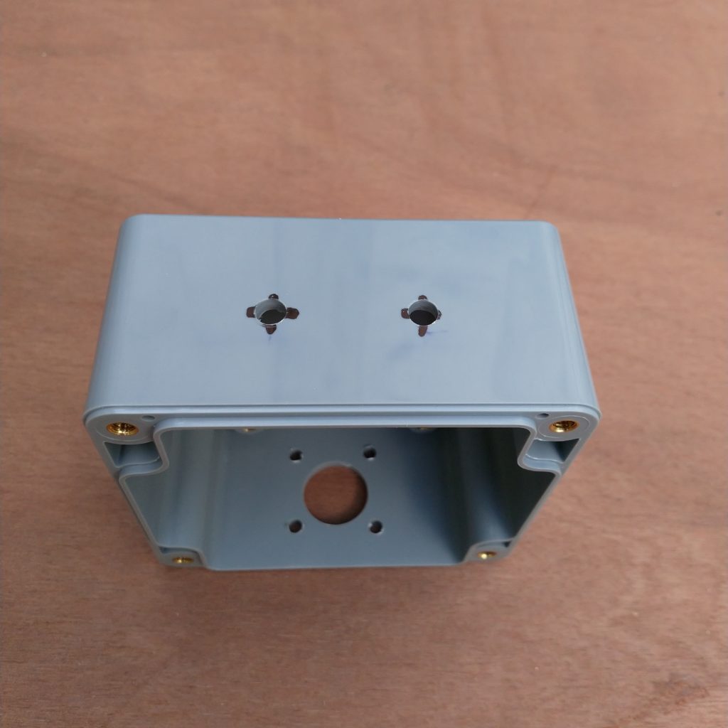
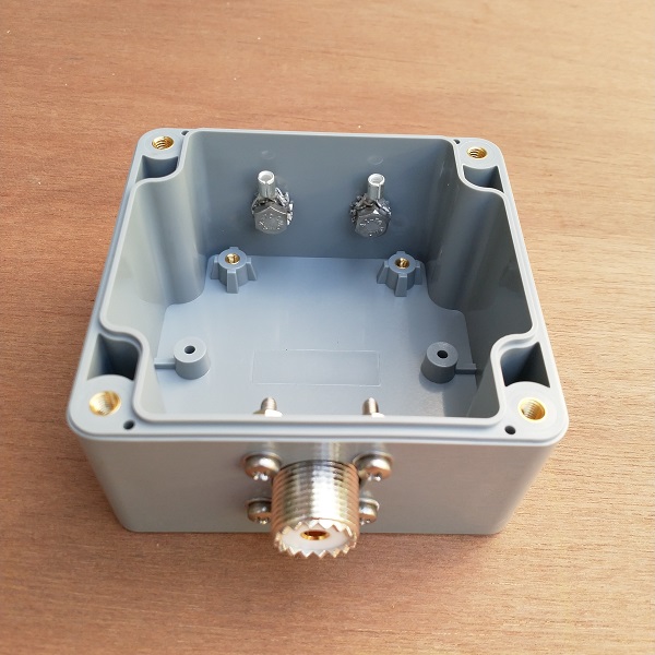
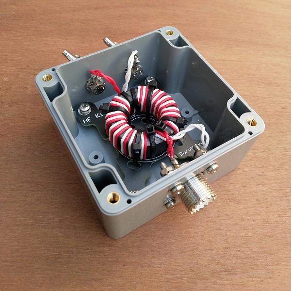
Mount the SO-239 chassis socket as shown in the figure below. This also applies to the connections for the ladder line.
The Ferrite Toroid
Now it’s time to start the most important part, the toroid core! For this antenna we will work with PFTE shielded silver plated copper wire, which is included in the DIY kit. The advantage of this PTFE shielded wire is that it is relatively thin, so the windings make maximum contact with the ferrite toroid and to each other. Now there are also other alternatives, but they don’t have this excellent insulation value (600-1000 Volt) and temperature properties of up to 200 degrees.
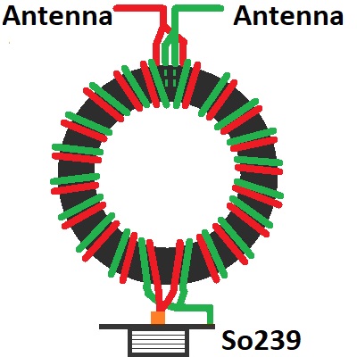
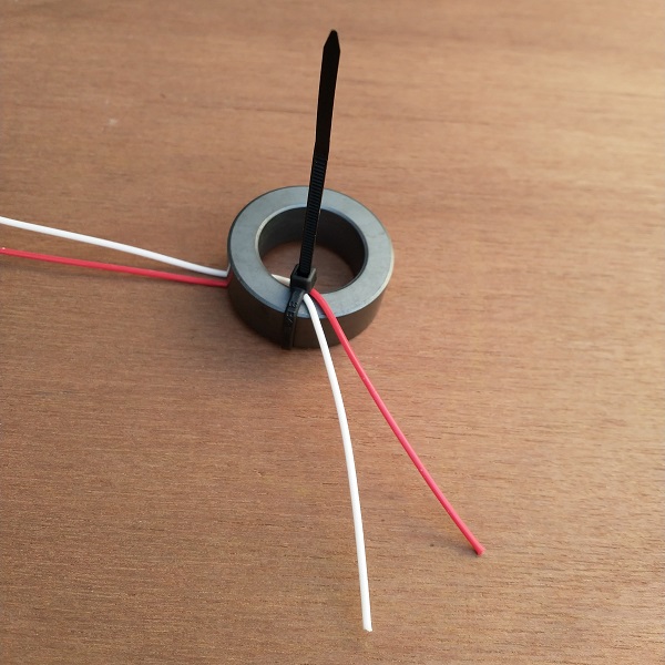
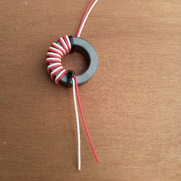
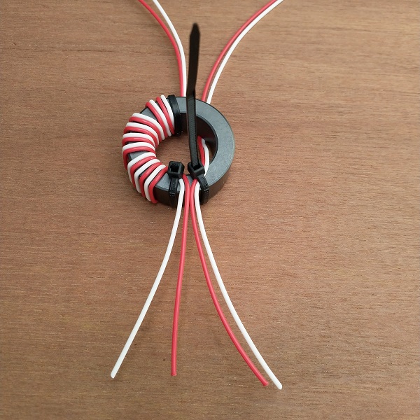
We start by securing two wires with the use of a cable tie. This makes it a lot easier. Then wrap the first 10 windings on half of the toroid as shown in the pictures below. Lay the windings tightly together, as space is limited at this toroidal core. Then wrap 10 windings on the second half. Note that the wires are wrapped exactly as in the example. Do not change colors or wrapping directions. At the bottom of the ring core are now the two red wires next to each other and the white wires on the outside. At the top of the ring core, this is exactly the other way around, there are the white wires next to each other in the middle and the red wires on the outside. If this is not correct, start again because then something went wrong.
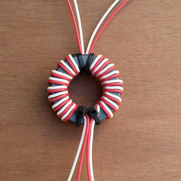
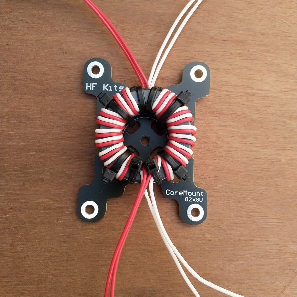
Secure the toroidal core to the provided mounting plate with the four cable ties. Then secure it in the housing with the M3 bolts.
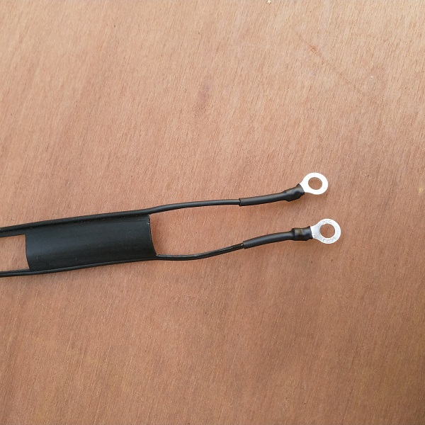
Connect the primary side of the toroid (bottom, where the red leads meet) to the SO-239 coax jack. The two red wires are soldered to the center pin of the coax connector and the white wires to the chassis socket with a cable lug. Remove the plastic parts from the cable lug so that a solid solder connection can be made. Now connect the other end of the BalUn to the terminals for the ladder line connections. Solder the two red cables to one connection point and the two white cables to the other connection point. Use the supplied M5 cable lug. Use the included toothed spring rings above and below the M5 cable lug, so the bolt will not rotate when you connect an antenna wire. These toothed spring rings are both mounted inside the enclosure. Place a flat washer on the outside and then attach a M5 nut. It is important to tighten the screws and bolts once more after soldering.
If necessary, test the 1:1 BalUn by putting a resistor of about 50 ohms (for example, 47 ohms) across the ladder line connections. In this way, the SWR meter should show a standing wave ratio of approximately 1:1.5 or lower.
Finishing the ZS6BKW, G5RV (junior/mini) antenna
The dimensions of the antenna and feed line is as follows:
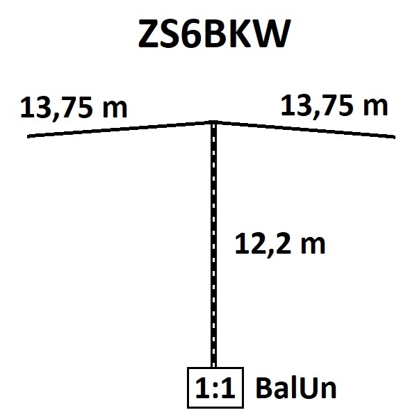
ZS6BKW: 12.20 mtr 450 Ohm ladder line. 2x 13.75 mtr dipole antenna
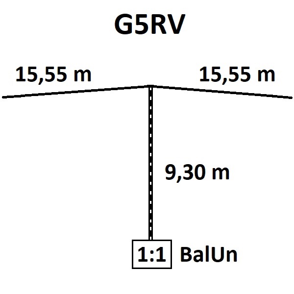
G5RV: 9.30 mtr 450 Ohm ladder line. 2x 15.55 mtr dipole antenna
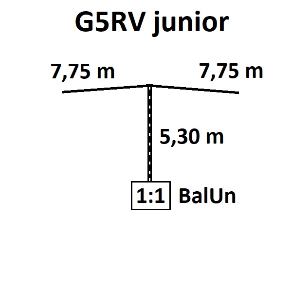
G5RV junior: 5.30 mtr 450 Ohm ladder line. 2x 7.75 mtr dipole antenna
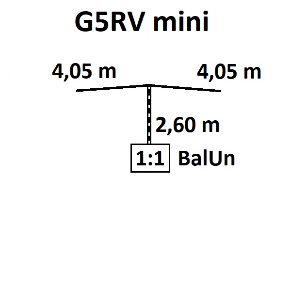
G5RV mini: 2.60 mtr 450 Ohm ladder line. 2x 4.05 mtr dipole antenna
The appropriate lengths are included with the antenna kit. (with some extra length)
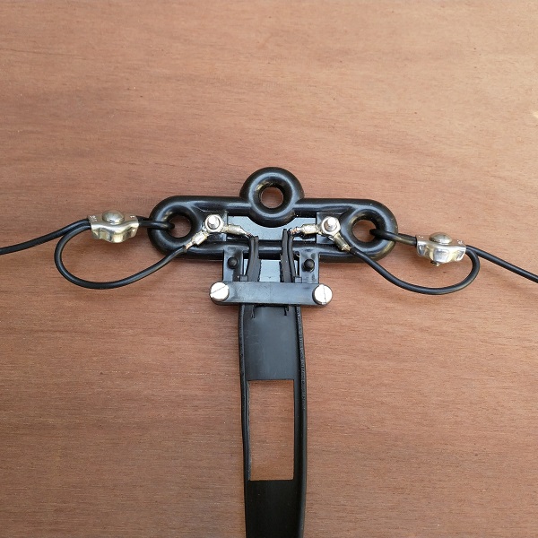
Connect the 450 Ohm ladder line and the two dipole halves to the feed point of the antenna as shown in the photo below. You can choose a solder joint or to use a crimping tool for the cable lugs. Personally, I favor soldering because crimping is prone to corrosion.
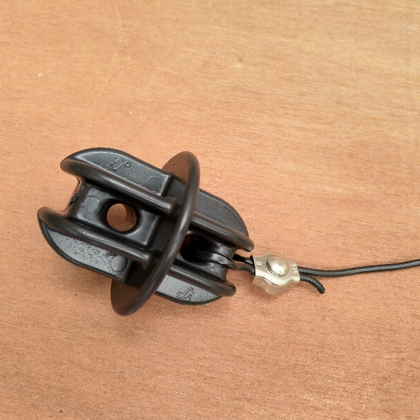
Then mount the insulators at both ends using the stainless steel cable clamps.
Mount the cable lug to the end of the ladder line. The antenna can possibly be tuned by shortening the 450 Ohm ladder line. In this case, it is advisable to install the cable lugs only after the 450 Ohm ribbon cable has been shortened. Connect the ladder line to the 1:1 BalUn.
Now the antenna can be mounted. Make sure the ladder line is placed somewhat clear of the environment and certainly metal objects. This has a direct effect on the SWR of the antenna. Also, make sure the ladder line does not cross the ground.