


Common mode filter applications
Why are common mode chokes useful? Common mode chokes are used in many applications. Here are some examples: for “End Fed” antennas so that the coax cable does not become part of the antenna. Ground plane antennas, so that the coax cable’s shield is not used as an extra radial. Between transceiver and amplifier to prevent earth-loops. Directly at the feed point of a dipole antenna (here it is often called a BalUn). Another situation where it may be useful is when you enter the House (shack). Because in many cases the coax cable does not always leave the antenna at an angle of 90 degrees with respect to the antenna radiator, sot the shield of the coax cable picks up the signal from the antenna directly.
The main reason for using a common mode choke is to ensure that the coax cable’s shield does not become part of the antenna system and will radiate unintentionally. This has all sorts of nasty effects, think of: interference issues, disrupted radiation pattern of the antenna and a higher noise level. This last point is because not only does the coax cable’s shield radiate when you transmit, but the shield also works as a receiving antenna. Because the coax cable often makes a considerable trip within the house, close to interference sources (mains, PLC etc…) It is useful to eliminate these sources of interference. Any way, Good reason to use a common mode choke.
The effect of a common mode choke can hardly be predicted. This depends on local circumstances. Think of: antenna type, antenna placement, type of feed line, feed line placement and especially local sources of interference. There are manufacturers that promise in advance a significant drop in interference, however this is not real. There are cases where the interference decreases by two to three S-points, but also cases where the filter has no noticeable effect.
Dipole Antenna
In case a good BalUn (which is actually a common mode filter) is used at the feed point of the antenna, in many cases an extra common mode filter is not necessary. It is important that the coax cable is stretched at least a quarter of a wavelength at right angles to the dipole antenna. If this is not the case, the antenna radiates directly into the coaxial cable sheath. In many cases, local circumstances simply do not allow this to be achieved. When entering the house, use a common mode filter to keep these unwanted coax shield current out of the house.
EndFed Antenna
In the case of the “End Fed” Antenna, the coaxial cable is used as a counter-capacity. Because the EndFed antenna in the feed point has a high impedance, the counter-capacitance requirements are not that high, but it is there. If you want to read more about this, check it out: EndFed antennas-a-critical-look It doesn’t have to be a problem if part of the coax cable is used as a counter-capacity, but often annoying effects occur. Think of interference, feedback, restless reception, RF in the shack etc. Especially this restless receiving is caused by the fact that the jacket of the coax cable in the house can pick up all kinds of disturbances, for example from the mains.
Where do you place such a common mode choke in the case of the EndFed antenna?
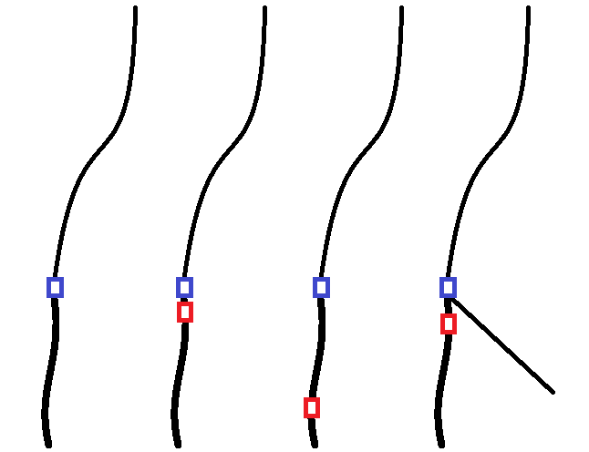
From left to right:
1: No common mode choke – If you are in an environment with little interference and do not work with high power, you can of course work without a choke. For example, if I work portable on the campsite, I don’t use a common mode filter.
2: Common mode chokes directly below the feed point – This is an unadvised choice. Because the filter is directly below the feed point, the counter capacitance is actually eliminated, which will cause the antenna to perform worse. Because the common mode filter is placed at a point where the antenna shows a high impedance, the filter will also perform much poorer. Example: A choke is used on an impedance point of 3000 Ohm. Also the impedance of common mode current at that point is 3000 Ohm. Then a voltage distribution takes place in which about half of the shield current will still be let through.
3: common mode filter at some distance from the feed point – This is a good choice. Because the filter is placed at some distance from the feed point, the antenna still has a piece of coax cable as counter capacity. An additional advantage is that the impedance of the antenna current has decreased, which will improve the performance of the filter. Take a length between 0.05 and 0.30 wavelength as a distance from the feed point.
4: Common mode filter in combination with a counter-capacity – This is also a good choice. Again, place the filter at some distance from the feed point. Because the sheath current has an alternative (the counter capacitance), the sheath current filter will perform optimally. Length counter-capacity 0.05 – 0.30 Wavelength.
Vertical Antenna
A quarter wave vertical antenna also needs multiple quarter wave radials. If no common mode filter is placed, the outside of the coaxial cable will also serve as radial. This in itself is not a problem, but we do not want to have these common mode currents in the shack. So also in this situation it is advisable to use a common mode filter.
Different common mode filters
There are three different commonly used common mode filters. The coax cable coiled into a coil, coax cable wrapped around ferrite, and bifilar windings around ferrite. These three popular common mode filters will now be treated individually. Measurements made by G3TXQ are used here. Hereby I would like to thank “Steve Hunt” for his permission to use this material. http://www.karinya.net/g3txq/chokes/
Coaxial coil filter
Below is an overview of some air coils wrapped from coax cable around for example PVC pipe. What immediately stands out is the poor bandwidth. So with this type of filter it is very important to choose the right diameter and the right number of windings, otherwise the filter will not work for the chosen frequency. Due to the limited bandwidth, this type of filter is unsuitable for multi-band antennas. Unfortunately, this type of filter also gives little real impedance but mainly inductive impedance. The advice is as follows: Preferably do not choose this type of filter!
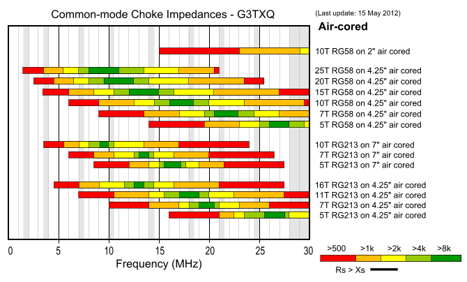
Source: Steve Hunt – G3TXQ
Conclusion: Easy to make, very poor bandwidth, little real impedance.
Coax ferrite filter
In the above example, the coaxial cable is wound around a PVC pipe (air coil). Now it is also possible to wrap coax cable around a ferrite core. The tables below by Steve Hunt (GX3TXQ) show the effect of the different ferrite cores and the number of windings.
Popular ferrite cores are discussed below. We start with the most famous type -43. This ferrite material is sold by different manufacturers. What immediately stands out is the bandwidth in relation to an air coil made of coax.
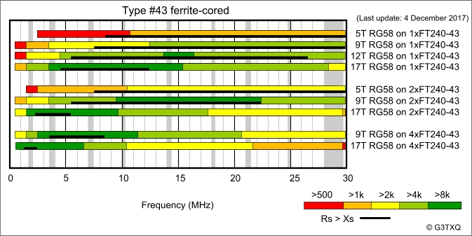
Source: Steve Hunt – G3TXQ
Below you can see an overview of the ferrite material 31. What immediately strikes you is that this material is better suited for the lower frequencies, think of the 160, 80, 60 and 40 meter band.
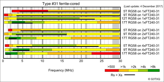
Source: Steve Hunt – G3TXQ
Type 61 is more suitable for the higher frequencies.
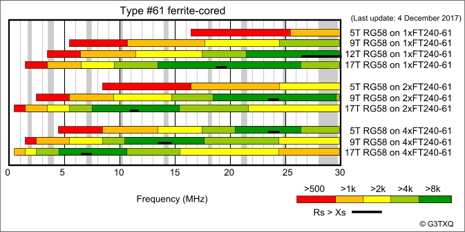
Source: Steve Hunt – G3TXQ
This last type 52 is not so easily available in Europe, but it does show some nice features.
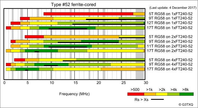
Source: Steve Hunt – G3TXQ
Conclusion:
Advantages: reasonably easy to make, band width suitable for multi-band antennas, good common mode attenuation, lots of real impedance. Disadvantage: the bandwidth still does not cover the full HF spectrum.
Bifilar wrapped ferrite filter
HF Kits chooses the bifilar common mode current filter. This type of filter shows optimal attenuation over a wide spectrum. For the winding wire, PTFE insulated silver plated copper wire is a good choice. This winding wire has a low resistance, can withstand high temperatures and has an insulation value of 600 Volt.
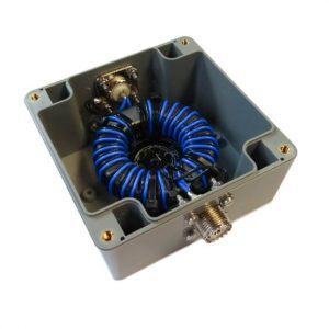
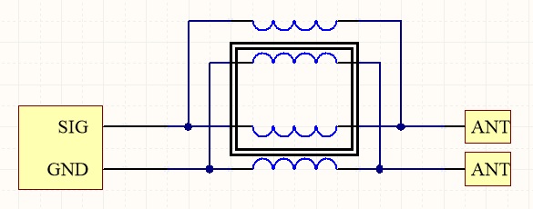
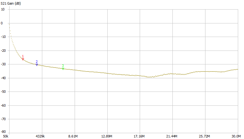
However, the impedance of two parallel wires with insulation is about 100 Ohm. Of course it should not be the case that the common mode filter disrupts the impedance of the supply line and antenna. So also the common mode filter must have an impedance of 50 Ohm. The picture below shows how two sets of bifilar windings are connected in parallel around the same toroidal core. Twice 100 ohms parallel makes 50 ohms. As a result, the impedance of the common mode filter is as it should be.
Below is a graph of the common mode attenuation. Core material FT240-43. Over the entire HF spectrum (3 – 30 MHz) an attenuation of at least 30 dB.
Conclusion
Advantages: Perfect damping, wide spectrum, ideal for multi-band use. Disadvantages: More difficult to make, relatively expensive toroidal core and winding wire!
Interested? Common mode filter DIY kit