


Are end-fed antennas really miracle antennas?
Anyone browsing the internet for experiences about end-fed antennas will come across a lot of information. Besides stories about fantastic DX connections and great reception reports, you can also find a lot of negative information. The truth will undoubtedly be somewhere in the middle, and this article will elaborate on this in detail.
Benefits
An advantage of end-fed antennas is of course the simplicity, especially for fieldwork this is a huge advantage. Put a telescopic mast against a pole, hook the antenna to the top and slide it out. You are on air within 5 minutes! An additional advantage is that the antenna can easily be polarized vertically. This makes the antenna convenient for (DX) long distance connections. Totally fantastic is the fact that the antenna is resonant at half a wavelength or a multiple of this wavelength. This makes the end-fed antenna perfect as a multi-band antenna. Just look at the following example: 20 meter wire is a half wavelength for the 40 meter band, two half wavelengths for the 20 meter band, four half wavelengths for the 10 meter band and 3 half wavelengths for the 15 meter band. Couldn’t be better, you say!?
Disadvantages
So far only benefits, what’s wrong with such an antenna? Unfortunately, there are very many cases known of people who suffer from a variety of interference when using end-fed antennas. Think EMI, restless reception, RF in the shack or all kinds of devices in the house that will lead a life of their own as soon as you get on air. There is only one clear reason for this and that is common mode current or imbalance in the supply line.
Imbalance… how?
In principle it does not matter whether you are working with open line, chicken ladder or coax cable, there is almost always an imbalance in the feed line with end-fed antennas. As a result, the feed line becomes an unintentional part of the antenna system, resulting in all of the aforementioned problems. In the case of an end-fed antenna fed with open-line, only one wire at the end of the feed line is connected to the half wave antenna. The other wire of the transmission line therefore is unconnected. It may be clear that at the end of the loose wire no current runs. Where should that current run? At the end of the other wire, current still runs into the antenna, otherwise the radiator wouldn’t do anything.
So at this point there is imbalance in the feed line. Now I can hear you thinking…. There is a voltage maximum at the end of the feedline and there is almost no current flow at this point, so does this matter? The minimum current difference at this position of the feedline does not do much, but is sufficient to create a significant difference in current a quarter of a wavelength further down the feedline. This imbalance in the feedline causes it to become part of the antenna, resulting in all the problems mentioned above.
But my end fed antenna is fed by coaxial cable?
End-fed antennas with an impedance transformer fed by coaxial cable probably don’t suffer from this? Unfortunately, this makes no difference. In this case, the outside of the coaxial cable is used as an antenna. See image below.
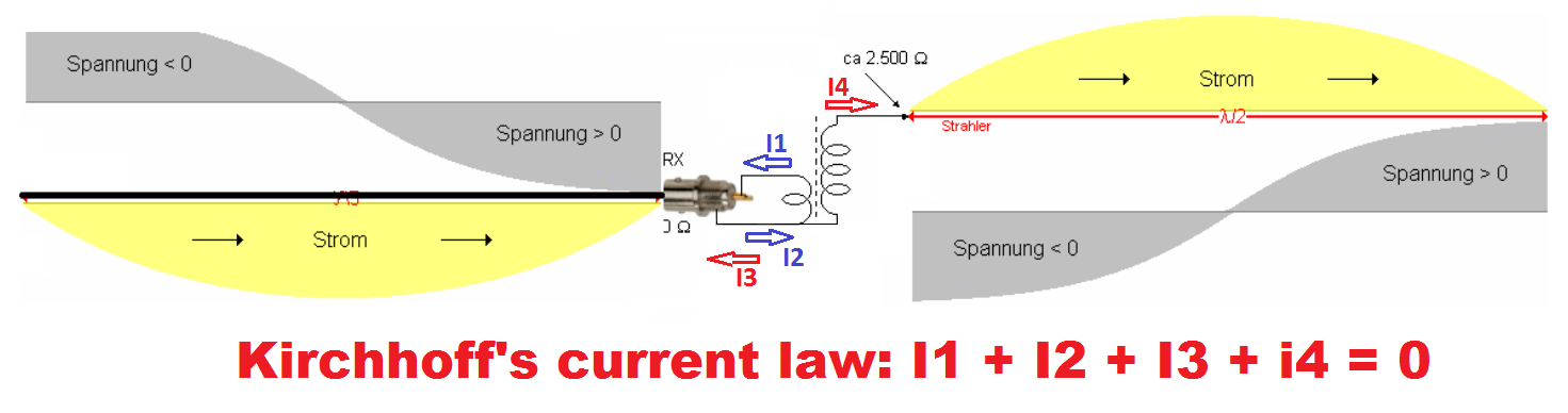
Common mode current in coaxial cable at end fed antenna (Source: Wolfgang Wippermann DG0SA)
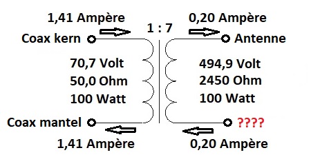
To clarify this, a schematic representation of the impedance transformer has been drawn below. The (left) primary side is fed with coaxial cable. The voltages and currents are shown at 100 Watt power. On the primary side you can see that 1.41 Amps goes into the transformer. With a winding ratio of 1:7 this results in an output current of 200 milliamps at the secondary (right) side of the transformer. Now the top side of the secondary side is connected to the antenna, so 200 milliamps will run here. At the bottom of the secondary side of the transformer a proportional amount of current will flow. With the “end fed” antenna, this is coupled to the coax shield (bottom primary windings). In practice this current will run over the outside of the coaxial cable.
It may be hard for some (including me) to imagine a coaxial cable can be seen as a cable with three conductors. The center core, the inside of the shield and thirdly the outside of the shield. If there is no common mode current, the currents in the center core and the (inner) shield are the equal. If common mode current does flow, it will look like this:
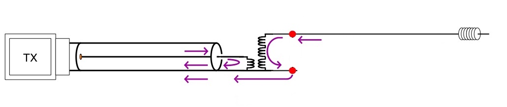
common mode current taken a closer look
Because the currents are not in balance, the coax cable will also radiate in this case. Unfortunately, this also applies to reception. So the antenna has an increased chance of picking up all kinds of interference in the near vicinity of the coax cable.
Practical examples
When I switched from a dipole antenna to an endfed antenna my interference problems started. I heard my own voice through the PC speakers. The dipole probably had a 1:1 BalUn which prevented common mode currents. The EndFed antenna does not have common mode current prevention, this causes RF in the shack through the outside of the coax cable.
After installing a common mode choke, the reception with my endfed antenna was a lot more quiet. It saves 3 S points! This can also be explained by the fact that the coax cable is part of the antenna. The feedline radiates when transmitting, but in case of imbalance it also works as a receiving antenna. All kinds of interfering signals in the house now radiate directly into the coax cable. Think also of the mains installation from which a lot of noise (PowerLineCommunication) comes nowadays.
The length of my coaxial cable affects the SWR. Because the coaxial cable serves as a counterpoise capacity, this is indeed the case.
Common mode choke
If you suffer from aforementioned problems than use a good common mode choke. Do not place the choke directly near the antenna feed point because the filter will hardly work. Most filters promise fantastic attenuation but measured at an impedance of 50 Ohm. Since the impedance is very high near the supply point, the filter will hardly work. Ideally, the filter should be placed a quarter of a wavelength from the feed point. At this point, the impedance is low again, which will make the filter work optimally. With multiband antennas this point is of course different for each band. In this case, use an average. For example, 6.5 Mtr. from the feed point at a 10, 20, 40 EndFed Antenna. Second choice would be 3.8 Mtr. meters away from the feed point are also a good option.
Counterpoise
At end fed antennas a certain current flows into the antenna, but according to “Kirchhoff’s current law” a proportional amount of current must flow somewhere else. Without counterpoise this will be the outside of the coax cable. A good way to minimize this is to create a counter-capacity. (Counterpoise) In the case of the End Fed antenna, you can simply make an extra connection and connect it to the coaxial cable shield. The counterpoise can be anything, think of: a piece of wire, the zinc gutter, the antenna mast or a ground pin. I prefer the combination of a common mode choke and counterposie because this way you force the antenna matchingbox to use the counter-capacitance instead of the coax cable.
Conclusion
Is the end fed antenna worthless or not? I absolutely don’t think the end fed antenna is worthless, otherwise I wouldn’t have offered it as a self-built kit in the shop. End Fed Antenna Kits. From a technical point of view, there is a lot to be noticed on the antenna as can be read above. Common mode current over the coax cable and therefore imbalance in the feed line are simply not desirable. On the other hand, it is an antenna that works great with a lot of people and can be used to make very nice DX. My personal advice is to use this antenna in the field without a common mode choke or other modifications, unless there are problems. When working at home with end-fed antennas, I would certainly opt for a good common mode choke and counterpoise capacitance. Do you have the space and possibilities for a symmetrical antenna then this is my preference.
Interesting links to this topic:
Current Flow Fundamentals for an “End-Fed” Antenna
http://www.wolfgang-wippermann.de/balun.pdf
https://www.w8ji.com/end-fed_1_2_wave_matching_system_end%20feed.htm
https://drive.google.com/file/d/0BwFicJLV0O4jVHdfanY0dDNtX0E/view