


Manual ATU Choke BalUn 800 Watts
This Manual ATU Choke BalUn 800 Watt will help you step by step in building the homebrew kit. If an Asymmetrical antenna tuner is used to feed a symmetrical feed line (and antenna), a BalUn is required. BalUn stands for Ballanced – Unballanced. This allows us to connect an unbalanced system (coaxial cable) to a balanced antenna system (e.g., dipole antenna). The ATU Choke BalUn 800 Watt is suitable for QRO use. The main reason to use a Choke BalUn is to ensure that currents in the feed line are of equal magnitude and flow in opposite directions. As a result, the feed line does not become part of the antenna and therefore will not radiate. This results in all sorts of unpleasant effects, such as: interference, disturbed radiation pattern of the antenna and noisy reception.
A ferrite toroid is used to enforce symmetry in the feed line. There is a lot of information on the Internet and even in literature about making a BalUn, but unfortunately there are also a lot of bad designs that hardly work. This design is one that has proven to work very good!
Use this design only in conjunction with an antenna tuner. This BalUn can handle a relatively wide range in terms of impedance, so it is not a 1:1 BalUn specifically for 50 Ohms.
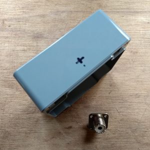
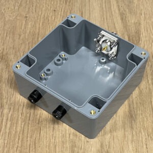
The enclosure
In this manual ATU Choke BalUn 800 Watts, we start by marking out and drilling the hole for the coax connector connection. The diameter of this hole should be 16 mm. Drilling these types of relatively large holes is easiest with a “slab drill.” (Google is your friend, if you’ve never heard of such a thing)
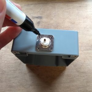
TIP: Place the hole as high as possible (directional lid) As a result, connecting later is easier.
After drilling the 16 mm hole, I placed the chassis part into the hole, to determine the location of the fixing holes. I picked a chassis part where I fix the part with 4 screws, but 2 screws could also work. These holes can be drilled with a 3,5 mm drill.
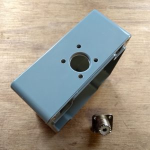
We then proceed to mark out and drill the holes for the symmetrical feed line connection. The hole for the banana plug connectors can be drilled with 6 mm. The place where the holes are drilled is to your own liking.
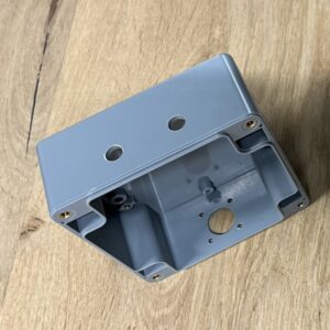
After all the holes are drilled all parts can be mounted as shown in the picture below.
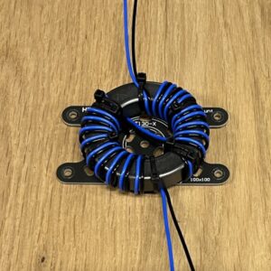
The Ferrite Toroid
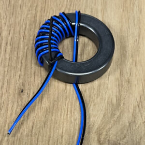
Now it’s time to start the most important part, the toroid core! For this antenna we will work with PFTE shielded silver plated copper wire, which is included in the DIY kit. The advantage of this PTFE shielded wire is that it is relatively thin, so the windings make maximum contact with the ferrite toroid and to each other. Now there are other alternatives but not with this excellent insulation value (600 – 1000 volts) and temperature properties up to 200 degrees.
We start by securing two wires using a cable tie, this makes it a lot easier. Keep to the bottom about 7 cm wire length, this is more than sufficient.
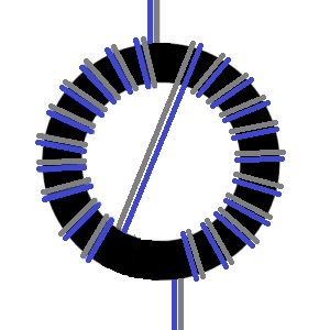
Then wrap the first 10 windings on half of the toroid as shown in the picture below. Make sure the windings are tightly placed together.
Now cross over and then wrap another 10 wraps on the second half. Note that the wires are wrapped exactly as in the example. Do not change colors or wrapping directions. Check now if everything is correct, if not start over because something has gone wrong.
Finishing up
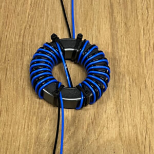
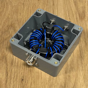
HF Kits developed a solution for fixing the toroid. From now on, a mounting plate including M3 bolts is included with each BalUn kit. With this mounting plate it is easy to connect the toroidal core with a few cable ties. First attach the ring core to the mounting plate before assembling it into the enclosure. See picture below.
Connect one end of the toroid to the (SO-239) coax connector. The blue wire on the centre pin of the coax connector and the black wire on the chassis terminal with a cable lug. Remove the plastic parts from the cable lug so that a solid solder connection can be made.
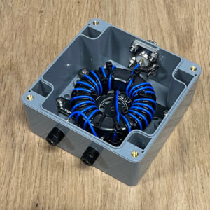
Now connect the other end of the transformer to the connections for the symmetrical feed line to the antenna. The blue wire to one side and the black wire to the other. (No matter, it is, after all, symmetrical). Use the banana plug connectors provided. On the inside, use the toothed spring washers provided.
Applications
If an Asymmetrical antenna tuner is used to feed a symmetrical feed line (and antenna), a BalUn is required. BalUn stands for Ballanced – Unballanced. As a result, we adapt an unbalanced feed system (coaxial cable and tuner) to a balanced antenna system (e.g., doublet antenna).
Doublet antenna
The Doublet antenna is widely used by Radio Amateurs. The advantage of this antenna is its multi-band use. So you can use the antenna on a variety of bands. Which bands exactly depends on the length of the antenna and feed line. Of course, the range of the antenna tuner (ATU) also plays a role.

Tips:
- Make the coaxial cable between the antenna tuner (ATU) and the ATU Choke BalUn as short as possible
- Use a common mode choke between the ATU and the transceiver
- Pass (if present) the control cable and power cable of the antenna tuner through a ferrite toroid several times
More info
The BalUn and impedance transformer What about exactly?