

The BalUn and impedance transformer What about exactly?
What is a BalUn
First of all, there is always a lot of confusion between the BalUn and the impedance transformer. BalUn stands for Balanced – Unbalanced. For example, you use a BalUn to adapt an unbalanced feed system (coaxial cable) to a balanced (symmetrical) antenna system (e.g., dipole antenna). No impedance matching takes place here because the antenna and feed system will both be about 50 Ohms. So this is clearly about the BalUn. You often read articles about a 1:4 BalUn, for example. This would mean that a 1:4 BalUn takes care of two functions, namely transforming the impedance by a factor of 4 and forming the transition between a Balanced and Unbalanced system. In most cases, such a combined system built around just one ferrite core does not work particularly well. The impedance transformation is often nice but the Balanced – Unbalanced function leaves much to be desired in many cases.
Why a BalUn?
The main reason to use a BalUn is to make sure that the coaxial cable does not become part of the antenna system and therefore radiate with it. This has all sorts of nasty effects, think of: interference issues, disrupted radiation pattern of the antenna and a higher noise level. This last point is because not only does the coax cable’s shield radiate when you transmit, but the shield also works as a receiving antenna. Reason enough to use a BalUn. The images below show that part of the antenna current does not choose the right leg of the dipole but chooses the outside of the coaxial cable. Care must be taken to keep the current in both dipole halves equal and to block a path to ground through the sheath of the coaxial cable.
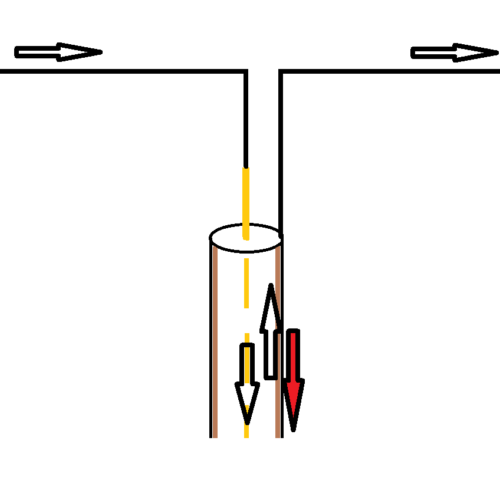
shield current across the coaxial cable
Antenna current at unbalance
Still not convinced?
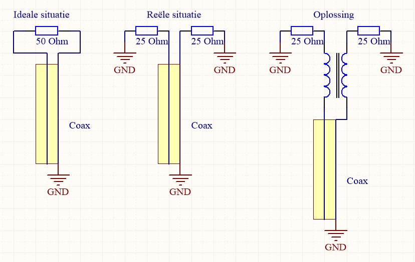
Take a look at the schematic representations of a dipole antenna below. On the left we see a schematic of what the ideal antenna would look like. A load of 50 ohms, independent of ground. In reality, there is indeed a connection to earth. Consider that a dipole antenna hanging low above the ground has a lower impedance than a dipole antenna hanging high above the ground.
Taking this phenomenon into account, the middle diagram more closely resembles reality. Now if we look at this middle schematic we notice that the resistor on the right is actually connected to ground on two sides! So why would the current still choose this resistor? This is because current chooses the path with the least resistance. In practice, some of the current will flow through the right dipole half and some across the outside of the coaxial cable back to ground.
The distribution of current depends greatly on the length of the coaxial cable. A dipole antenna has the greatest risk of imbalance with half-wavelength coaxial cable. So imbalance occurs, resulting in all the aforementioned misery. A solution must be found as in the diagram on the right, and we will go into this in more detail.
What does a BalUn need to meet?
A good BalUn should ensure that the current in both antenna halves is equal (balanced) and that no current can drain through the outside of the coaxial cable to ground. By running two conductors in parallel around a toroidal core, both currents are forced to be equal. As long as the incoming and outgoing currents of both conductors are equal to each other, the magnetic flux in the core will also behave oppositely and cancel each other out. As a result, the BalUn has no effect on the signal current. Any common mode current does travel in the same direction as one of the two conductors so the flux in the core also has the same direction. This flux accumulates and causes a high impedance for the common mode current preventing it from flowing.
Windings of two conductors parallel to each other are also called bifilar windings. It is important that both conductors are laid tightly side by side because the characteristic impedance is then about 50 ohms. So this only works with, say, enameled copper wire that is tight together. If insulated wire is used, the spacing is just a bit greater, making the characteristic impedance more likely to go toward 100 ohms. It is also possible to wrap coaxial cable around a toroidal core, then of course the impedance remains just 50 Ohms.
Unfortunately, there are limitations to enameled copper wire in bifilar windings. The insulation is minimal and therefore can easily blow through.
How do we solve this problem?
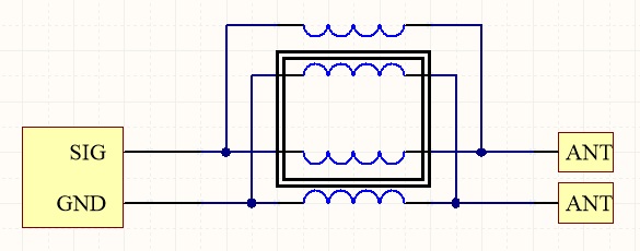
It is better to use insulated wire. HF Kits chooses PTFE insulated silver-plated copper wire. This winding wire has a low resistance, can withstand high temperatures and has an insulation value of 600 Volt. However, the impedance of two parallel wires with insulation is about 100 Ohm. Of course, the BalUn should not interfere with the impedance of the antenna. So the BalUn must also exhibit an impedance of 50 ohms. The picture below shows how two sets of bifilar windings are connected in parallel around the same toroidal core. Twice 100 ohms parallel makes 50 ohms. This returns the impedance of the BalUn to what it should be.
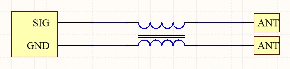
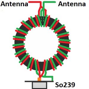
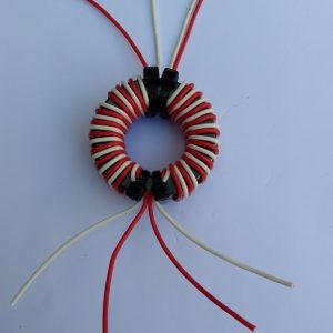
Practically, this looks like the image below.
Which Ring Core
For a good BalUn or impedance transformer, it is best to use Ferrite. Iron powder material has too low an AL value, therefore a huge number of windings are needed to achieve a nice result (I will come back to this later). A large number of windings, especially in an impedance transformer, creates a lot of capacitance between the windings. This affects the impedance especially at the higher frequencies. So ferrite material must be used that gives sufficient self-inductance at a small number of windings. The frequency range at which a ferrite core works well depends on the ferrite material chosen; this too must of course be taken into account.
Some examples of good core material for broadband applications:
Amidon -43 (1 / 30 MHz)
Amidon -61 (10 / 100 MHz)
Ferroxcube 4C65 (2 / 30 MHz)
Why an impedance transformer?
So much for the BalUn, but when does the impedance transformer come into play? impedance transforming is necessary if the antenna impedance does not match the impedance of the transceiver and feed line. In many cases one wants to work with a 50 Ohm transceiver and 50 Ohm coaxial cable up to the antenna, then if the antenna also shows 50 Ohm, a BalUn will suffice. Suppose working with a “Full wave Quad antenna” or a “Full wave Delta Loop Antenna” then the antenna impedance will be about 100 Ohms. In this case, a 1:2 impedance transformer will be needed to transform 100 ohms to 50 ohms. If an “Of Center Fed Antenna:” (Windom antenna) is used, the impedance will be between 200 and 300 Ohms. Now a 1:4 or 1:6 impedance transformer is chosen.
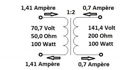
The winding ratio of the adjustment transformer determines the impedance adjustment. If a winding ratio of 1:2 is chosen, the voltage will be doubled and therefore the current halved. This results in an impedance matching of 1:4.
Example: 1:2 winding ratio gives 1:4 impedance matching:
In practice
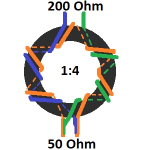
Below is an illustration of a balanced 1:4 impedance transformer with a winding ratio of 1:2. Here, 6 primary windings and 12 secondary windings are used. Of course, another number of windings can be chosen as long as the ratio remains correct.
Number of windings
The winding ratio may determine impedance matching but there are countless winding possibilities with this ratio. In our above example, one could literally choose one primary winding and two secondary windings. Finally, this gives a ratio of 1:2. Another possibility is 10 primary windings and 20 secondary windings. To determine the number of windings, we need to go a little deeper.
A rule of thumb that you come across everywhere is as follows: The reactance XL (AC resistance) of the transformer should be at least 5 times greater than the impedance to be matched. This is necessary to minimize the influence of the transformer so that reasonable efficiency is achieved. Reactance depends on the core material, number of windings and frequency of operation. So the number of windings is very important here. A 1:4 adjustment transformer must be rated on the secondary side for a 200 Ohm load. Now according to previously mentioned rule of thumb, the reactance (alternating current resistance) of the secondary side of the transformer should be at least (200 x 5) 1000 Ohms.
How do we calculate that?
Each type of core has a corresponding AL value. This value says something about the relationship between the number of windings and the resulting self-inductance of the transformer. The AL value depends not only on the core material but also on the dimensions of the core.
L(nH) = (N²) × AL
In the formula above, L is the self-inductance in nH (nano Henry), N is the number of windings and AL is the relative self-inductance of the core.
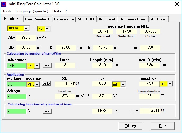
Below is an example of 8 windings around a 140-43 toroid with an AL value of 885 nH/N²
L(nH) = (8²) × 885 = 56640 nH ==> 56,6 µH
Now that we have calculated the self-inductance of the secondary side, the reactance for a given frequency can be determined. In the following calculation, I assume the 80 meter band, with a frequency of 3.6 MHz.
XL = L * 2 * π * f ==> XL = (56,6 * 10^-6) * 2 * π * 3.600.000 = 1280 Ohm
“Mini Ringkern Rechner” can also be used. This handy program automatically calculates the above calculations. In this program, simply select the toroid after which the AL value is immediately known. If some additional data is entered, the reactance at a given frequency is also determined.
Download link to Mini Ringker Rechner: Click here!!!
Then just a few more windings?
The number of 8 secondary windings will be sufficient in the case of the 80-meter band. After all, 1280 Ohms is well above 1000 Ohms. Should we want to use this transformer for the 160 meter band we would run into trouble. The obvious thing to think now is to use as many windings as possible because the reactance will always be amply met.
Unnecessary windings unfortunately also bring disadvantages. This is because the windings also behave like small capacitors with respect to each other. More windings means more unintended capacitance in the transformer. This is an undesirable effect that will occur mainly above 15 MHz. The result is poor SWR on the high bands. So on this point, a compromise will have to be sought. More windings means a higher reactance at the lower frequencies but a less favorable SWR at the higher frequencies.
When do I use a BalUn and when do I use an impedance transformer?
In the case of switching from an unbalanced feed line (coax) to a balanced antenna (dipole) then you will need to use a Balun. Both systems are about 50 Ohms. As a result, no impedance transformation is required and only a BalUn is desired.
When is a BalUn alone not enough? In the case where an unbalanced feed line (coax) is used to feed a balanced antenna with a different impedance. In fact, not only must there be a transition from unbalanced to balanced but also the impedance must be matched. The best method in this case is to use both, so first a BalUn and then a symmetrical impedance transformer. Thus, two toroids are used. Keep the distance between the BalUn and the adjustment transformer as short as possible.
In the case where only an impedance tranformation needs to be made but both systems are unbalanced (asymmetrical) then only an impednace transformer is sufficient. Consider a ground plane antenna, end fed antenna or long wire antenna with 1:9 UnUn. A common mode current filter (choke) further up the feed line is then recommended.