

Manual 1:9 UnUn for long-wire antennas
The 1:9 UnUn is wrongly called a 1:9 BalUn in many sources. In my opinion, this is incorrect because there is no transformation to a balanced antenna system. The feed point of a long-wire antenna is nothing more than a broadband impedance transformer. In the case of a 1:9 UnUn, the power line (coax) impedance of 50 ohm will be transformed up to an impedance of 450 Ohm. After all 50 x 9 = 450. This means that the length of the long-wire antenna must be chosen in such a way that the impedance in the feeding point on as many frequency bands as possible is about 450 ohm. Over the wire length more later. The transformer consists of 8 primary windings and 24 secondary windings. This gives a ratio of 1 to 3. The voltage is therefore three times higher and the current is three times lower than the power source. This gives an impedance adjustment of 3 x 3 = 9. The impedance of 50 Ohm is thus increased a factor of 9, this makes 450 Ohm. The entire 1:9 UnUn assembly will be wrapped around a FT240-43 ferrite toroidal core with broadband properties. In this Manual 1:9 UnUn, you will be helped step by step in the construction.
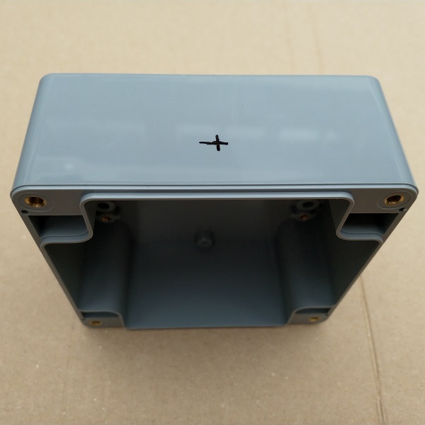
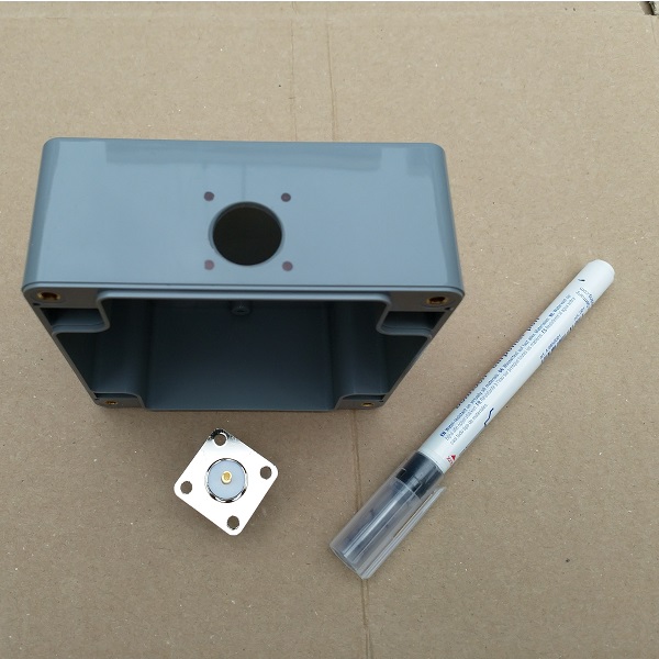
The enclosure
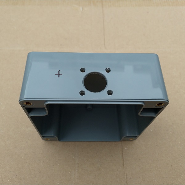
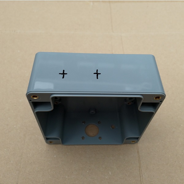
We start by marking and drilling the hole for the coax connector. The diameter of this hole should be 16 mm. This is a large hole and therefore it is easiest to create it with a ‘sheet step drill’. (Google is your friend, if you’ve never heard of such a thing.) Drill the hole 1.5 cm from the top, this makes connecting later easier. After the 16 mm hole has been drilled, the chassis part can be put upside down in the hole for drawing the 4 attachment holes.
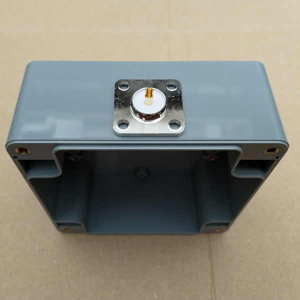
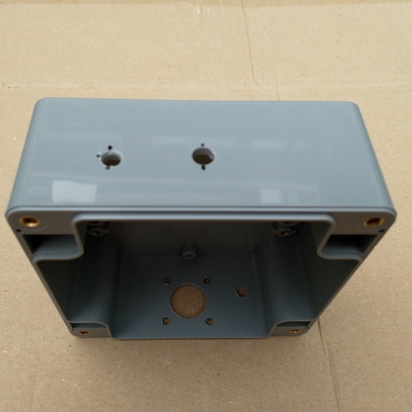
Now drill the four fastening holes with a 3.5 mm drill. In addition to the coax connector, drill a 5 mm hole for the countercapacity connection. Once this is done, we’ll turn the box over. Now we continue with the marking and drilling of the holes for the long wire antenna connection and the strain relief. It is especially recommended to use a strain relief for antennas that will be placed for the long term of even permantently. The hole for the stainless steel eye should be drilled with a 6 mm drill and the hole for the antenna connection should be drilled with a 5 mm drill. Personally, I think it’s nice to attach the strain relief in the middle. The place where the holes are drilled is to your own liking.
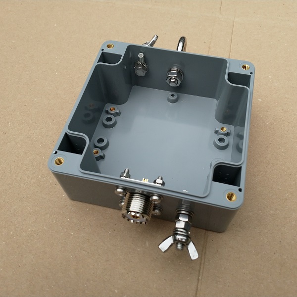
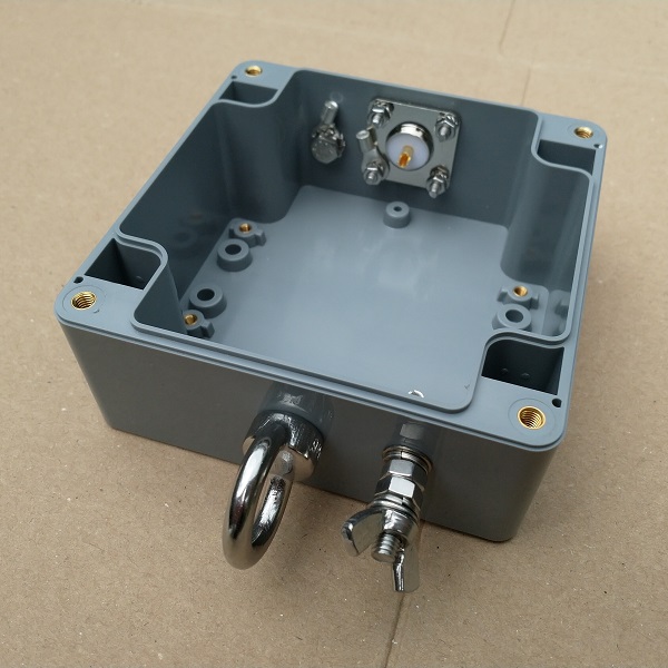
After drilling all the holes, we can find out if everything fits the way it should. Here you can see the result of drilling the holes and tightening the screws. When attaching the 5 mm bolts on the inside of the box, use two tooth-spring rings. One above and one below the cable lug, this will prevent it from rotating later when connecting the antenna wire or counter poise capacitance. Use a tan to pull the blue plastic part of the cable lug.
The Impedance transformer
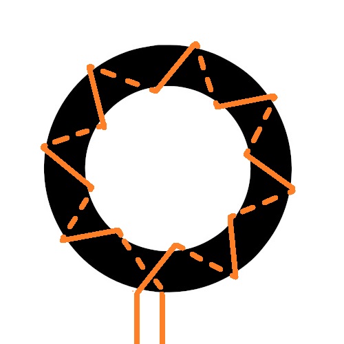
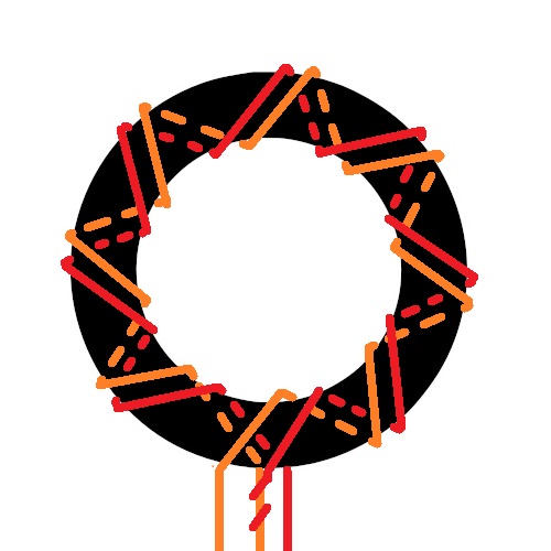
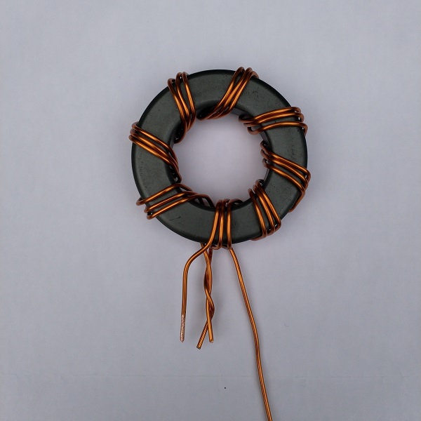
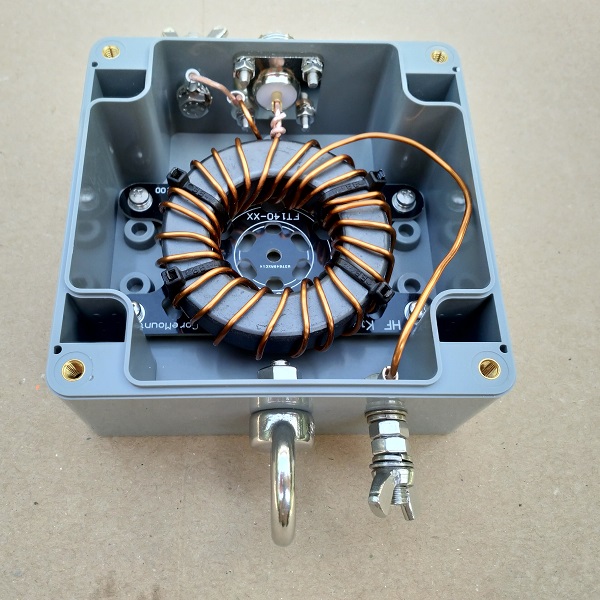
The Manual 1:9 UnUn continues with the following section. The time has come to begin the 1:9 impedance transformer. Cut off 55 cm of wrapping wire. Let about 5 cm of wire protrude before you start wrapping. Wrap this wire 8 times evenly around the core as in the first image. If it’s all right, you’ll have about 120 cm of wrapping wire left. Twist this loosely around the piece of wire of the first winding as on the second picture. Now wrap this thread 8 times around the core parallel to the first wire. If you have been around 8 times you can immediately make 8 windings parallel to the first two wires, this starts at the point where the red wire goes over in the color purple on the schematic. This is purely to clarify the schematic image, but the thread does not have to be soldered or anything like that. Now the wrapping of the 1:9 UnUn is ready. We now see three connections at the bottom of the core. From left to right: Ground -> 50 ohm coax core -> long wire antenna. At a later stage we turn the core around, so don’t get confused by this.

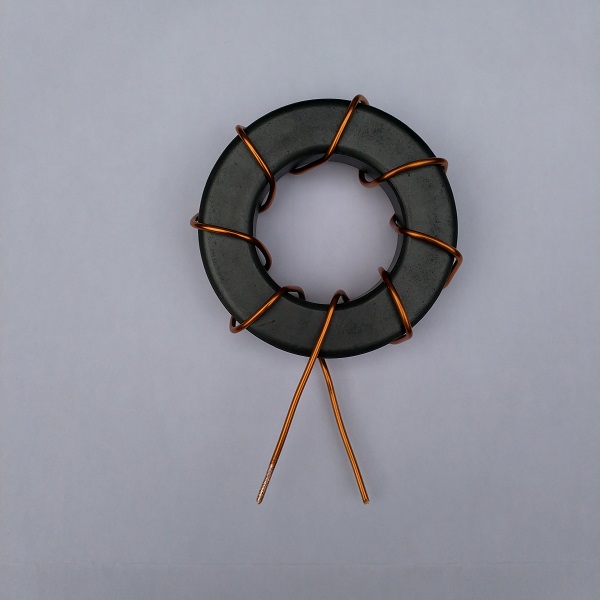
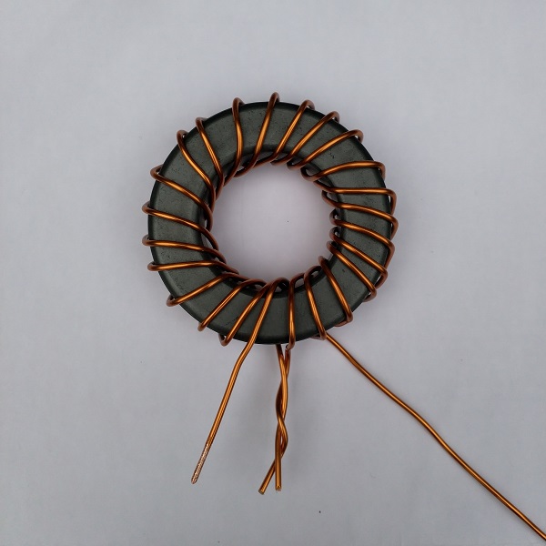
Below you will find the same story again in photo view. It’s noticeable that I’ve wrapped the wires parallel together here. This makes wrapping easier. At a later stage, it is easy to distribute the windings evenly over the core.
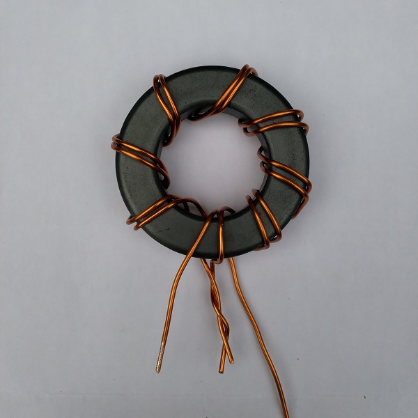
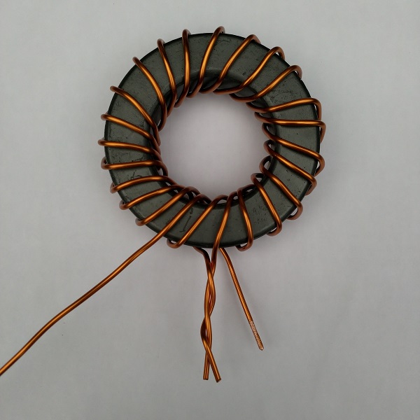
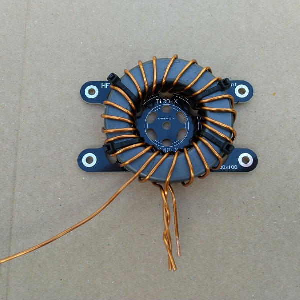
See below the result. After the windings are evenly distributed, we turn the core around! The left-to-right connections are now: Longwire – > Coax core – > ground/countercapacity. Because we have flipped the core, this sequence of connections corresponds to the connection points on the enclosure. Now secure the core to the four-cable binder attachment plate.
Finishing up
Now carefully adjust the core in the housing and cut all connection wires to size. After all wires are the correct length, the insulation should be removed from the wrapping wire. This is an important job, if this does not happen well soldering is almost impossible and an unintentional resistance arises. Dilating the enamel insulation layer is possible with a sharp knife, coarse sandpaper or a small file.
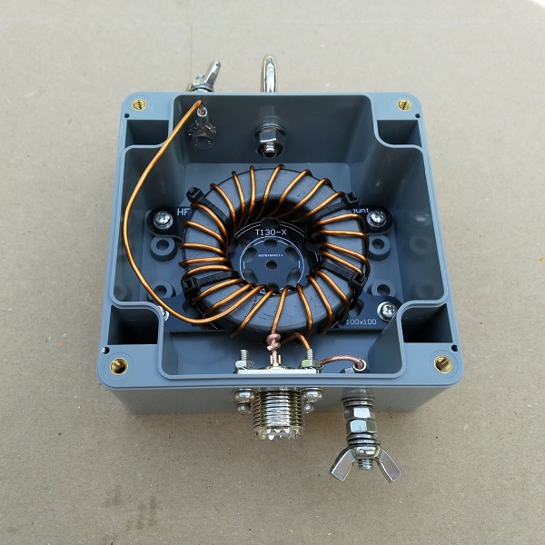
After the connecting wires have been properly removed from the insulation, the connections can be soldered. Use a soldering iron with sufficient power. Now it is time to attach the lid with accompanying weir (resembling a white string). So far the manual 1:9 UnUn.
Applications
There are a lot of antenna variants to think of in combination with the 1:9 UnUn. In principle, it is possible to mount any length of wire, but in practice it appears that there are favorable and less favorable wire lengths. The wire can be mounted horizontally, vertically, as a sloper, Inverted L and as Inverted V. The long-wire antenna has the advantage that when using the right length wire, it can be used on many HF bands. This means that the antenna on many HF bands shows a reasonable SWR and often the internal tuner of the transceiver is sufficient.
Wire length
A lot has been written about the antenna length of the long-wire antenna. The basic rules are as follows: Stay away from quarter and half wavelengths on the frequency bands where you want to work. At the lowest frequency at which you want to be active, approach at least a quarter wavelength. So not exactly a quarter wavelength! In my opinion, the ideal wire length will be slightly different for everyone in practice. Nevertheless, the Internet is a beautiful source of inspiration. Lengths mentioned a lot: 7 Mtr, 9 Mtr, 16.1 Mtr, 18.7 Mtr, 27.5 Mtr, 38 Mtr.
This is at least a nice starting point to start the experiments. Here’s some inspiration:
http://www.hamuniverse.com/randomwireantennalengths.html (lengths in feet)
https://vk6ysf.com/longwire_antenna.htm
http://webclass.org/k5ijb/antennas/End-fed-multiband-antenna-BalunDesigns.htm (lengths in feet)
Need counter poise capacity?
A long-wire antenna requires a countercapacity. This can be resolved in several ways:
- coax cable of the power line as countercapacity (high risk of interference problems)
- earth pen or earth net as countercapacity
- one or more pieces of random wire length as countercapacity
- a sinking gutter, steel fencing or anything else made of metal
Common mode choke
TIP: With a 1:9 UnUn and long wire antennas always use a common mode choke. The main reason to use a common mode current filter is to ensure that the coax cable does not become part of the antenna system and therefore starts to radiate unwanted. This has all sorts of nasty effects, think of: interference, EMI, RFI disrupted radiation pattern of the antenna, restless noise level. This last point is because not only does the coax cable’s shield radiate when you transmit, but the shield also works as a receiving antenna. You can link the common mode choke directly to the 1:9 UnUn with a PL-male-male connector or leave some distance. This piece of coax cable between the 1:9 UnUn and the common mode filter then serves as a countercapacity.