


Manual common mode current filter 1 – 30 / 3 – 30 MHz
There are many types of common mode chokes available, HF Kits opts for a common mode choke with bifilar windings for optimal filtering.
The main reason for using a common mode choke is to ensure that the coax cable’s shield does not become part of the antenna system and will radiate unintentionally. This has all sorts of nasty effects, think of: interference issues, disrupted radiation pattern of the antenna and a higher noise level. This last point is because not only does the coax cable’s shield radiate when you transmit, but the shield also works as a receiving antenna. Because the coax cable often makes a considerable trip within the house, close to interference sources (mains, PLC etc…) It is useful to eliminate these sources of interference. Any way, Good reason to use a common mode choke.
A ferrite ring core is used, which allows for maximum attenuation of common mode current Its main features are maximum attenuation of common mode current with minimal loss of the signal. This design is one that works proven very well!
The effect of this common mode choke with bifilar windings is difficult to predict. This depends on local circumstances. Think of: antenna type, antenna placement, type of feed line, feed line placement and especially local sources of interference. There are manufacturers that promise in advance a significant drop in interference, however this is not real. There are cases where the noise level decreases by two to three S points, but also cases where the filter has almost no effect.
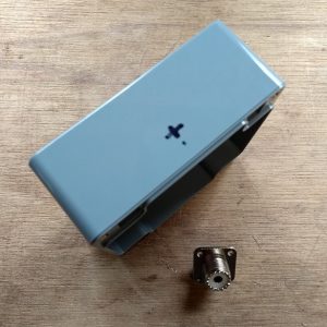
The enclosure
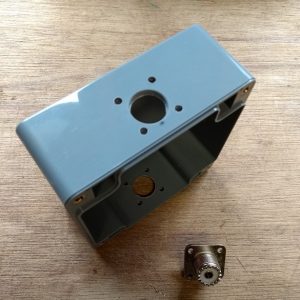
We start by drilling the holes for the coax connector connection. The diameter of this hole should be 16 mm. This is a large hole and therefore it is easiest to create it with a ‘sheet step drill’. (If you have never heard of that, Google is your friend for looking up what you need)
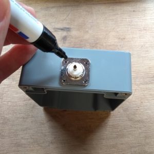
After the 16 mm holes have been drilled, I put the chassis part in the hole to determine the position of the fasteners holes. I picked a chassis part where I fix the part with 4 screws, but 2 screws could also work. These holes can be drilled with a 3,5 mm drill.
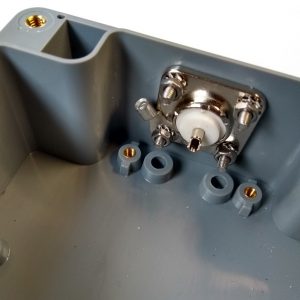
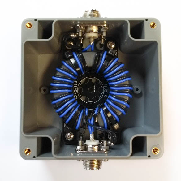
After all the holes are drilled, both connectors can be mounted as shown in the picture below. Don’t forget to mount the M3 cable eyelet to one of the four screws.
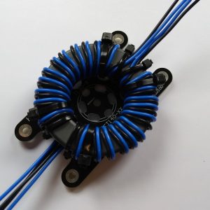
The Ferrite Toroid
Now it’s time to start the most important part, the toroid core! For this antenna we will work with PFTE shielded silver plated copper wire, which is included in the DIY kit. The advantage of this PTFE shielded wire is that it is relatively thin, so the windings make maximum contact with the ferrite toroid and to each other. Now there are also other alternatives, but they don’t have this excellent insulation value (600-1000 Volt) and temperature properties of up to 200 degrees.
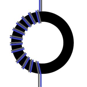
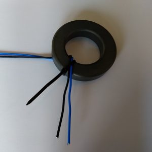
We start by securing two wires with the use of a cable tie. This makes it a lot easier. Keep to the bottom about 5 cm wire length, this is enough length.
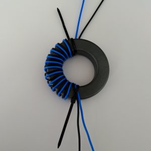
Then wrap the first 12 windings on half of the toroid as shown in the picture below. Make sure the windings are tightly placed together.
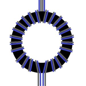
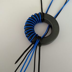
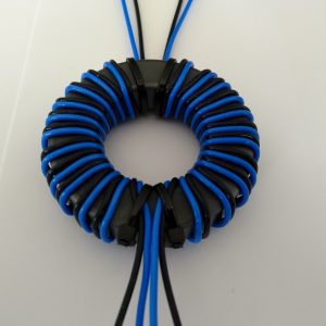
Then wrap 12 windings on the second half. Note that the wires are wrapped exactly as in the example. Do not change colors or wrapping directions. At the bottom of the toroid the two blue wires are next to each other and the black wires on the outside. At the top of the ring core, this is exactly the other way around, there are the black wires next to each other in the middle and the blue wires on the outside. If this is not correct, start again because then something went wrong.
Finishing up
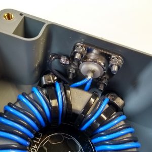
HF Kits developed a solution for fixing the toroid. From now on, a mounting plate including M3 bolts is included with each BalUn kit. With this mounting plate it is easy to connect the toroidal core with a few cable ties. First attach the ring core to the mounting plate before assembling it into the enclosure. See picture below.
Connect the primary side of the ring core (bottom, where the blue wires are next to each other) to the coax connector. The two blue wires at the center core of the coax connector and the black wires on the chassis part with a cable lug. Remove the plastic parts from the cable lug so that a solid solder connection can be made.
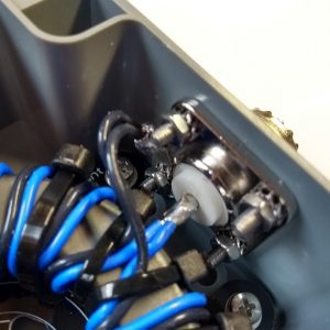
Now connect the other side of the toroid core to the coax connector. The two blue wires at the center core of the coax connector and the black wires on the chassis part with a cable lug.
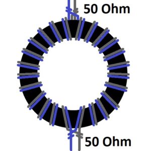
The impedance transformer can possibly be tested by putting a resistor of approximately 50 Ohm (e.g. 47 ohm) over the output connector. Then the SWR meter should show a standing wave ratio of 1:1. Of course, a “dummy load” can also be used for testing purposes.
Applications
Common mode chokes are used in many applications. Here are some examples: for “End Fed” antennas so that the coax cable does not become part of the antenna. Ground plane antennas, so that the coax cable’s shield is not used as an extra radial. Between transceiver and amplifier to prevent earth-loops. Directly at the feed point of a dipole antenna (here it is often called a Current BalUn). Another situation where it may be useful is when you enter the House (shack). Because in many cases the coax cable does not always leave the antenna at an angle of 90 degrees with respect to the antenna radiator, sot the shield of the coax cable picks up the signal from the antenna directly.