


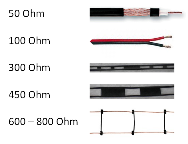
Different feed lines
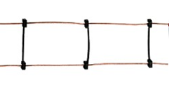
The feed line is used to transport the transmitted signal from the transceiver to the antenna. Upon receiving, this is of course in reverse order. On the picture below you will find different feed lines. This technical article will be limited exclusively to the impedance of the feed lines. These supply lines below have a characteristic impedance. What exactly does this impedance mean? If I measure such a cable with the Ohm meter, all cables below will indicate almost 0 (zero) Ohm. Then what’s the difference?
Current and voltage
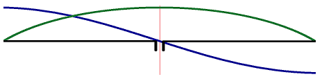
In a dipole antenna (single conductor) the impedance will vary greatly depending on the measuring point. We have all seen the picture below. The current is indicated here with a green line and the voltage with the blue line. In the middle of the dipole antenna, the voltage is relatively low and the current high. At the ends, the voltage is high and the current is low. The ratio between voltage and current is actually the impedance. This is also why an “End Fed Antenna” needs an impedance transformer. After all, the current at the end (or beginning) of the antenna is quite low and the voltage high.
Feed line impedance
With a dipole antenna, for example, this impedance variation is a desired effect. This is often different in the feed line. If we connect a dipole antenna of 50 Ohm to the feedline, we like to see that at the end of the feedline the impedance is still 50 Ohm. The impedance that belongs to a feedline does not say anything about the resistance of the chosen conductor, but says something about the load impedance to be connected. In our case, this is usually the antenna.
What determines this impedance?
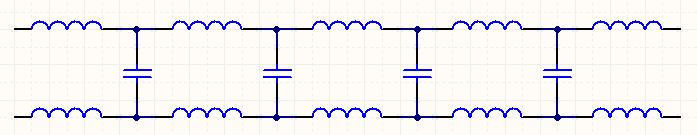
This is hard to explain, but I’ll give it a try. Is this beyond your imagination, don’t panic. There are some practical examples later. A single conductor will always behave somewhat like a coil (inductive). Two conductors parallel to each other will always have a certain mutual capacity. A feed line can therefore be represented as shown below. The characteristic impedance is determined by an equilibrium in the induction of the (imaginary) coil and the capacity of the (imaginary) capacitor. If the conductors have a larger distance between them, the capacity will decrease. This strongly influences the impedance. On the first picture of this article it is clear to see that as the distance between the two increases, the impedance will also increase.
Impedance match
If antenna and feedline have the same impedance then any length of feedline can be used. This is, for example, the case with a 50 Ohm dipole antenna with associated 50 Ohm coax cable.
In case the load (antenna) and supply line match, the length of the supply line will not affect the impedance!
No impedance match
If the feed line and antenna impedance do not match then a strange effect occurs. The feedline will then behave as in the example with the dipole antenna. The ratio between voltage and current will vary depending on the measuring point. So the impedance has become length-dependent.
If load (antenna) and feedline do not match, the length of the feedline will affect the impedance!
If the antenna and feedline have a different impedance, there are two conditions in which the impedance adjustment can be easily predicted.
Half wavelength feed line and no impedance match
so: Lline length = λ/2
If the feed line has half a wavelength, the input impedance is equal to the output impedance:
Zin = Zload
Pay attention to the shortening factor! In case coaxial cable is used, a significant shortening factor is applied. For example, at RG-58, this is 0.66
Quarter wavelength feedrline and no impedance match
so: Lline = λ/4
If the feed line has a quarter wavelength the following formula can be applied:
Zin = Zline²/Zload
Pay attention to the shortening factor here too! In case coaxial cable is used, a significant shortening factor is applied. For example, at RG-58, this is 0.66
Example 1
- 50 Ohm load
- 50 Ohm coaxial cable
- Length unknown
Because the load and feed line have the same impedance, the length will have no influence on the impedance.
Example 2
- 100 Ohm Load (For Example, DeltaLoop Antenna)
- 50 Ohm coaxial cable
- Length half wave
Half wave length applies: Zin = Zload
Because exactly half a wavelength coax cable is used in this example, an impedance of 100 Ohm will also be seen at the end of the coax cable.
Zin = Zload –> Zin = 100 Ohm
Example 3
- 100 Ohm Load (For Example, DeltaLoop Antenna)
- 50 Ohm coaxial cable
- Length quarter wave
Because the impedance of the coax cable and the antenna do not match, in many cases an impedance transformation will occur. In this example a quarter wavelength coax cable is used where the following formula applies:
Zin = Zline²/Zload
Zin = 50² / 100
Zin = 2500 / 100 = 25 Ohm
Example 4
- 100 Ohm Load (For Example, DeltaLoop Antenna)
- 75 Ohm coaxial cable
- Length quarter wave
Because the impedance of the coax cable and the antenna do not match, in many cases an impedance transformation will occur. In this example a quarter wavelength coax cable is used where the following formula applies:
Zin = Zline²/Zload
Zin = 75² / 100
Zin = 5625 / 100 = 56,25 Ohm
An impedance change doesn’t always have to be a disadvantage. In this example this impedance change is used to more or less feed the 100 Ohm antenna to the impedance that the transceiver likes ( 50 Ohm).
Example 5
- 50 Ohm load (dipole antenna)
- Feed line 600 Ohm open line
- Length quarter wave
In this example a quarter wavelength open line is used where the following formula applies:
Zin = Zline²/Zload
Zin = 600² / 50
Zin = 360000 / 50 = 7200 Ohm !!!
This example clearly shows that a deviating impedance in antenna and supply line can have major consequences. A dipole antenna of 50 Ohm fed with a quarter wavelength open line with an impedance of 600 Ohm shows a huge change! 7200 Ohm! A decent antenna tuner is needed to bring this impedance back to 50 Ohm.
Antenna Analyzer
The above examples show that a mismatch between antenna and supply line can cause a significant impedance change. This also means that in many cases an antenna analyzer does not show the antenna impedance. Nowadays there are antenna analyzers on the market that can “calculate away” this impedance change in the feed line. The analyzer should then be calibrated to the appropriate feed line. If you do not have access to such an advanced analyzer use than half a wavelength feed line. Of course you can also use a multiple length of these. So half a wavelength, whole wavelength, one and a half wavelength…
For example, a piece of coax cable of 13.94 meters is suitable to take measurements on the 10, 15, 20 and 40 meter band. This can be explained as follows:
7.1 MHz –> 42,25 mtr. –>half wavelength = 21.12 mtr.
14,2 MHz –> 21,13 mtr. –>full wavelenght = 21.13 mtr.
21,3 MHz –> 14,08 mtr. –>one and a half wavelenght = 21.12 mtr.
28,4 MHz –> 10,56 mtr. –>two full wavelengths = 21.12 mtr.
Considering the shortening factor of RG-58 coax cable of 66%, this equates to a length of: 21.12 x 0.66 = 13.94 mtr.
The exact length may vary slightly in practice!
Conclusion
- Impedance change caused by the feedline does not always have to be a disadvantage.
- With a half wave length feedline no impedance adjustment takes place. (note shortening factor!)
- With a quarter wave length feed line an impedance change takes place according to the discussed formula.
- At a random length, the impedance change is difficult to determine.
- Be careful with an antenna analyzer! What the antenna analyzer indicates does not always have to be the antenna impedance. In this case, use a half wavelength feed line.