

Manual 1:1 BalUn 800 Watt for dipole antennas
This manual 1:1 BalUn 800 watts helps you step by step with building the DIY kit. If a dipole antenna is fed with a coaxial cable from the transceiver it is always recommended to use a BalUn. BalUn means: Balanced to Unbalanced. This enables us to adapt an unbalanced fed system (coaxial cable) to a balanced antenna system (dipole antenna). The 1:1 BalUn 800 Watt is suitable for QRO use. The main reason for using a BalUn is to ensure that the coaxial cable does not become part of the antenna system and therefore radiates with it. This has all sorts of nasty effects, think of: interference, EMI, RFI disrupted radiation pattern of the antenna, restless noise level. This last point is because not only does the coax cable’s shield radiate when you transmit, but the shield also works as a receiving antenna.
A ferrite toroid is used, which prevents common mode currents. The main characteristic of a good BalUn is maximum common mode current reduction and minimal loss of the differential current. There is a lot of information on the Internet and even in literature about making a BalUn, but unfortunately there are also a lot of bad designs that hardly work. This design is one that has proven to work very good!
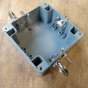
The enclosure
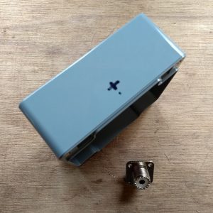
In This manual 1:1 BalUn 800 Watt, we start by marking and drilling the holes for the antenna connections and the tensile stools. The diameter of this hole should be 16 mm. This is a large hole and therefore it is easiest to create it with a ‘sheet step drill’. (If you have never heard of that, Google is your friend for looking up what you need)
TIP: Place the hole as high as possible (directional lid) As a result, connecting later is easier.
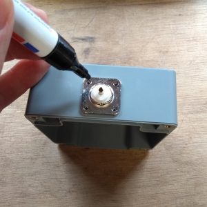
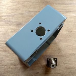
After drilling the 16 mm hole, I placed the chassis part into the hole, to determine the location of the fixing holes. I picked a chassis part where I fix the part with 4 screws, but 2 screws could also work. These holes can be drilled with a 3,5 mm drill.
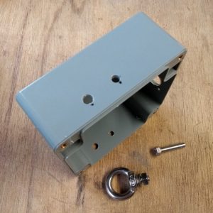
We continue by marking and drilling the holes for the antenna connections and the tensile stools. Especially for longer or permanent antennas it is advisable to use a tensile stool. The hole for the stainless steel eye is drilled with a 6 mm drill and the hole for the antenna connections is drilled with a 5 mm drill. The place where the holes are drilled is to your own liking. After all the holes are drilled all parts can be mounted as shown in the picture below.
The Ferrite Toroid
Now it’s time to start the most important part, the toroid core! For this antenna we will work with PFTE shielded silver plated copper wire, which is included in the DIY kit. The advantage of this PTFE shielded wire is that it is relatively thin, so the windings make maximum contact with the ferrite toroid and to each other. Now there are also other alternatives, but they don’t have this excellent insulation value (600-1000 Volt) and temperature properties of up to 200 degrees.
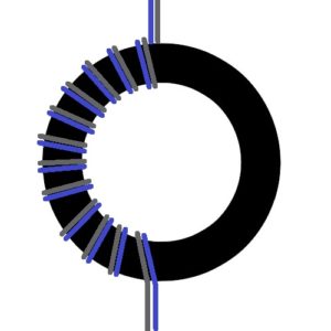
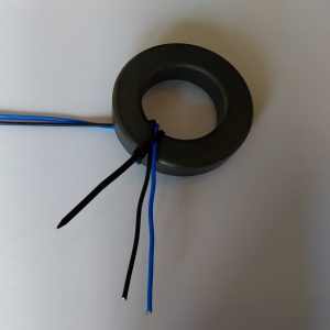
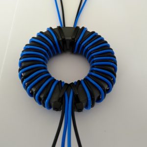
We start by securing two wires with the use of a cable tie. This makes it a lot easier. Keep to the bottom about 7 cm wire length, this is more than sufficient.
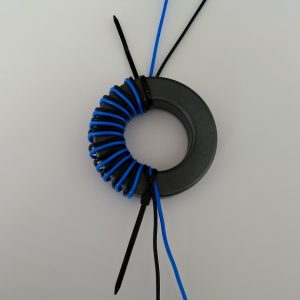
Then wrap the first 12 windings on half of the toroid as shown in the picture below. Make sure the windings are tightly placed together.
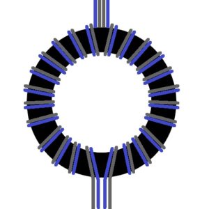
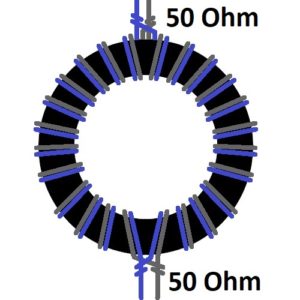
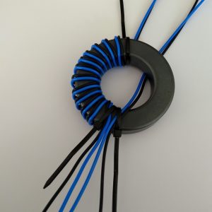
Then wrap 12 windings on the second half. Note that the wires are wrapped exactly as in the example. Do not change colors or wrapping directions. At the bottom of the toroid the two blue wires are next to each other and the black wires on the outside. At the top of the ring core, this is exactly the other way around, there are the black wires next to each other in the middle and the blue wires on the outside. If this is not correct, start again because then something went wrong.
Finishing up
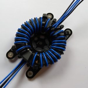
HF Kits developed a solution for fixing the toroid. From now on, a mounting plate including M3 bolts is included with each BalUn kit. With this mounting plate it is easy to connect the toroidal core with a few cable ties. First attach the ring core to the mounting plate before assembling it into the enclosure. See picture below.
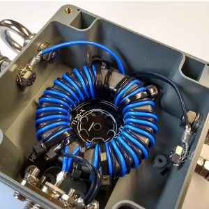
Connect the primary side of the ring core (bottom, where the blue wires are next to each other) to the coax connector. The two blue wires at the center core of the coax connector and the black wires on the chassis part with a cable lug. Remove the plastic parts from the cable lug so that a solid solder connection can be made.
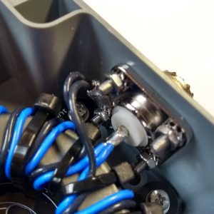
Now connect the other side of the transformer to the connections for the wire antenna. The two blue wires to one side and the two black wires to the other side. Use the supplied M5 cable lug. Also remove the plastic part here. For this you can use the included toothed spring washers and place them below and above the M5 cable lugs (which means that these are inside the housing and not on the outside). In this way, the bolt will never turn when the connection to the antenna wire is established. Place a flat washer on the outside and then attach a M5 nut.
The impedance transformer can possibly be tested by putting a resistor of approximately 50 Ohm (e.g. 47 ohm) over the two dipole connectors. In this way, the SWR meter should show a standing wave ratio of approximately 1:1.5 or lower. Testing with a half-wavelength wire (in case of a dipole twice a quarter wave) is of course also a good alternative!
Applications
There are many antenna variants possible with a 1:1 BalUn. Of course, the antenna should have an impedance of approximately 50 ohms in the fed point. It is easily to create a single band dipole antenna. There are also multi-band variants to be devised. This can be done by connecting multiple dipole antennas to the same feed point (cat’s whisker). It is also possible to choose for traps or coils, or even a combination of previously mentioned possibilities.
Single band Dipole Antenna
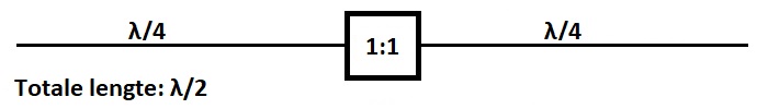
If two wires of each a quarter wavelength are connected to the BalUn, a single band antenna is made of a half wavelength in total.
The wavelength and antenna length can be found in the table below, but can also be calculated by using the following formula:
     u
λ = ---
     f
In this formula λ is the wavelength in meters, u the light velocity in meters per second, and f the frequency in Hertz. The following example determines the wavelength of the 20 meter band. The frequency of 14.1 MHz is used in this case. First, some zeros are striped away against each other.
     u     300.000.000      300
λ = --- = ------------- = ------ = 21.28 mtr
     f     14.100.000      14.1
We have now calculated the full wavelength. To get a quarter wave, the result must be divided by 4. To get a half wavelength, the result must be divided by two. Antenna wire always has a certain shortening factor. This depends on the conductive material, the diameter and the isolation. Generally the shortening factor will be about 95%. So the total length of our 20 meter dipole antenna (half wave) will be calculated as follows:
     u / 2             300.000.000 / 2              150
λ = ------- * 0,95 =  ----------------- * 0,95 =  ------ * 0,95 = 10,1 mtr
       f                 14.100.000                14.1
Wavelength table
| Band | Frequntie MHz | Golflengte λ | Halve golflengte λ/2 | Kwart golflengte λ/4 |
|---|---|---|---|---|
| 160 meter | 1,81 MHz | 165,75 Meter | 82,87 Meter | 41,44 Meter |
| 80 meter | 3,6 MHz | 83,33 Meter | 41,66 Meter | 20,83 Meter |
| 60 meter | 5,35 MHz | 56,07 Meter | 28,04 Meter | 14,02 Meter |
| 40 meter | 7,1 MHz | 42,25 Meter | 21,13 Meter | 10,56 Meter |
| 30 meter | 10,1 MHz | 29,70 Meter | 14,85 Meter | 7,43 Meter |
| 20 meter | 14,15 MHz | 21,20 Meter | 10,60 Meter | 5,30 Meter |
| 17 meter | 18,1 MHz | 16,57 Meter | 8,29 Meter | 4,14 Meter |
| 15 meter | 21,2 MHz | 14,15 Meter | 7,08 Meter | 3,54 Meter |
| 12 meter | 24,95 MHz | 12,02 Meter | 6,01 meter | 3,00 Meter |
| 10 meter | 28,4 MHz | 10,56 Meter | 5,28 Meter | 2,64 Meter |
Multi Band Dipole Antennas
Cat’s whisker Dipole Antenna
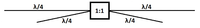
It is also possible to pair multiple half-wave dipole antennas to the same feed point of the antenna. The lengths are chosen in the same way as with the above single band dipole antenna. This way the dipole antenna can be used on multiple bands. The distance between the two dipole antennas can be quite small, this has no negative effect on the SWR. The radiation pattern of the antenna is slightly affected. If you like to prevent this then make the distance (angle) as large as possible. It is also possible to place one part horizontally and one part as inverted-V as shown on the image below. It is also possible to add another dipole antenna to this two band dipole antenna. There are several examples of 4 or 5 band cat’s whisker antennas available on the Internet.
Fine tuning
Place the complete cat’s whisker dipole antenna with some extra wire length at the desired spot. Always start by tailoring the longest dipole for the lower frequencies. Always remember: you can cut it off, you can’t trim it back? So don’t cut too excited. If the longest dipole shows an acceptable SWR on average, it can be started to tailor the short dipole. In practice, the antenna will be slightly shorter than a single band dipole. Always make sure you cut the same length of both sides to keep the antenna symmetrical.
Dipole with coils
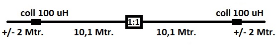
By applying coils in the dipole antenna something special happens. Because the coil for the higher frequencies is a high impedance, the last piece of wire (after the coils) does not count for this higher frequencies. The total antenna including coils only participates for the lower frequencies. In the case of the 20 and 40 meter band variant, the piece of 10.1 meters of wire works for the 20 meter band. The entire antenna is mechanically 13 meters long but for the 40 meter band, the antenna including coil has an electric length of 20 mtr. This means it creates a half wave length for the 40 meter band. A disadvantage of working with shortened antennas is the limited bandwidth on the low frequency bands.
Examples
80/40/(15) Multi band Dipole antenna
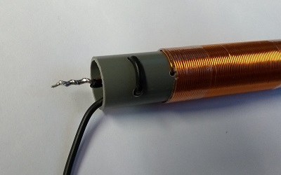
A 100 uH coil is made by using a 19mm PVC pipe. With 0.5 mm (0.2 mm2) winding wire make 150 windings tightly together.
The coils
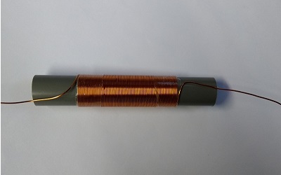
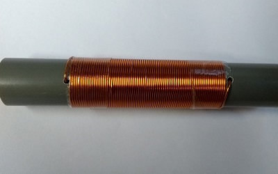
Try to wrap the coil as tight as possible, so there will not be any space left between the windings. Then fix the entire piece with some tape. Continue by drilling two small holes, right next to the coil, where you can stick the ends of the wire in.
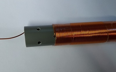
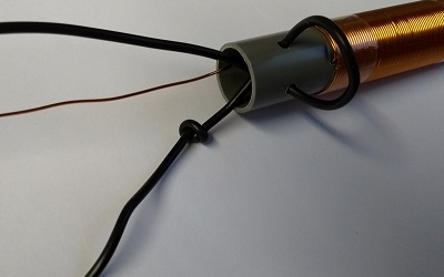
The next step is to drill two more holes as shown in the photo above. These holes will be used to put the wire through, which will be used as the strain relief. Finish this step by tying a knot in the wire and pulling it tight.
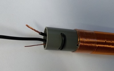
The excess wire can be cut off from the winding wire and the antenna wire. Leave just enough so there will be enough material for soldering. Make sure that the winding wire is completely stripped of the enamel layer. This can easily be done with a sharp knife or some sandpaper. Now solder the wire to the coil and put this into the pipe.
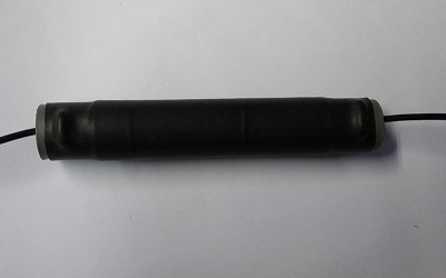
Now apply the heat shrink and heat evenly until the heat shrink fits nicely.
Fine tuning
Place the complete dipole antenna with some extra wire length at the desired spot. The first step is to then tailor the wire for the higher frequencies. These are the wires directly connected to the BalUn. Always remember: you can cut it off, you can’t trim it back? So don’t cut too excited. If the upper band shows an average of an acceptable SWR, it can be started to tailor the pieces of wire after the coils. Always make sure you cut the same length of both sides to keep the antenna symmetrical.
More info
The BalUn and impedance transformer What about exactly?