


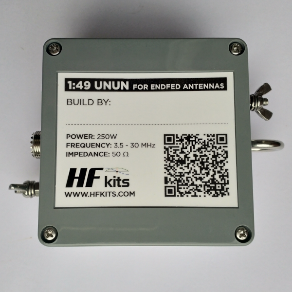
Manual impedance transformer for 250 watts End Fed Antenna’s
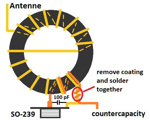
The feeding point of a multiband End Fed antenna is practically a wide band impedance transformer. This means that the end fed wire antenna, which has a very high impedance of around 2500 Ohm, is transformed to an impedance of 50 Ohm. This impedance suits best to most tranceivers. The transformer consists of 2 primary windings and from 14 secondary windings. This gives a ratio of 1 to 7. The voltage is therefore seven times higher than the source voltage and the current is seven times lower than the source current. This results in an impedance transformation of 7 x 7 = 49. That increases the impedance of 50 Ohm by a factor of 49, that makes it a total of 2450 Ohms. To create the impedance transformer, you wrap everything aroung a ferrite toroid that has broadband properties.
The above number of windings can be used for antennas used for the 10, 12, 15, 17, 20, 30 40 and 80 meter band. If the antenna is used only for the lower frequencies (80 and 160 meters) the same ratio is used with 3 primary and 21 secondary windings.
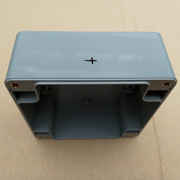
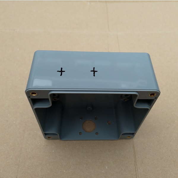
The enclosure
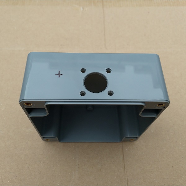
We start by marking and drilling the hole for the coax connector. The diameter of this hole should be 16 mm. This is a large hole and therefore it is easiest to create it with a ‘sheet step drill’. (Google is your friend, if you’ve never heard of such a thing.) Drill the hole 1.5 cm from the top, this makes connecting later easier. After the 16 mm hole has been drilled, the chassis part can be put upside down in the hole for drawing the 4 attachment holes.
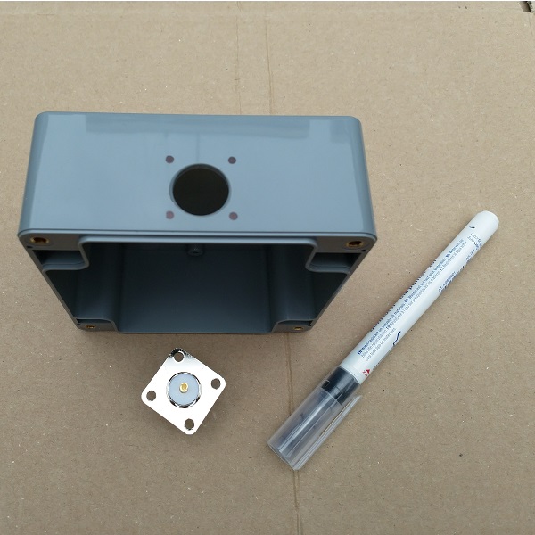
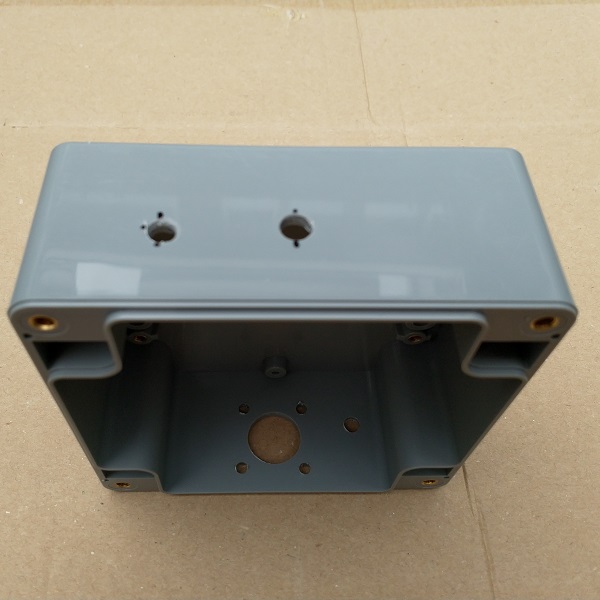
Now drill the four fastening holes with a 3.5 mm drill. In addition to the coax connector, drill a 5 mm hole for the countercapacity connection. Once this is done, we’ll turn the box over. Now we continue with the marking and drilling of the holes for the long wire antenna connection and the strain relief. It is especially recommended to use a strain relief for antennas that will be placed for the long term of even permantently. The hole for the stainless steel eye should be drilled with a 6 mm drill and the hole for the antenna connection should be drilled with a 5 mm drill. Personally, I think it’s nice to attach the strain relief in the middle. The place where the holes are drilled is to your own liking.
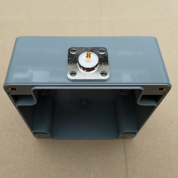
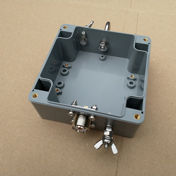
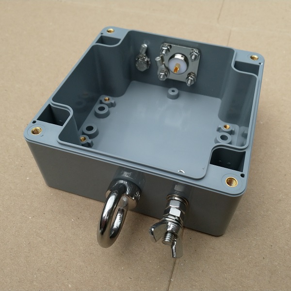
After drilling all the holes, we can find out if everything fits the way it should. Here you can see the result of drilling the holes and tightening the screws. When attaching the 5 mm bolts on the inside of the box, use two tooth-spring rings. One above and one below the cable lug, this will prevent it from rotating later when connecting the antenna wire or counter poise capacitance. Use a tan to pull the blue plastic part of the cable lug.
The Impedance transformer
We are going to start on the impedance transformer.
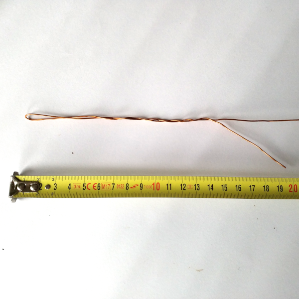
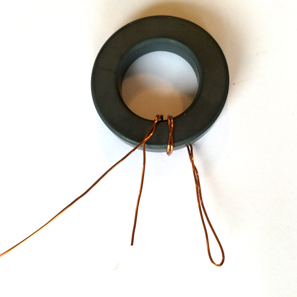
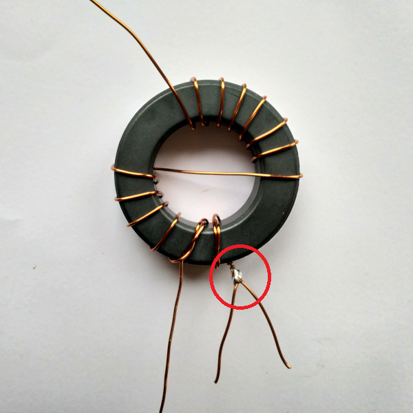
Fold about 20 cm of the enameled copper wire in half and lightly twist the first 15 cm to hold it together. Make sure to not twist the copper too much, because this might create strange effects in the transformer at a later point. Now take the point where the two pieces of wire become one and place this on the toroid. Now wrap the double part twice around the core. Then wrap the other 12 windings as shown in the pictures below. Cross over to the other side after the sixth wind.
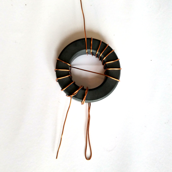
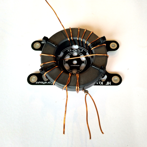
Now cut the loop of the double winding wire end. This creates two loose wires. Remove the insulation from the winding wire close to the core. The insulation material can be removed with a sharp knife or sandpaper. Do this carefully, if the wires do not make good contact, the antenna will not work. Now wrap the wires around each other a few turns and solder them. Now the toroidal core is ready and can be fixed on the special toroidal mounting plate. If all went well then the transformer now looks the same as in the pictures below.
Finishing up
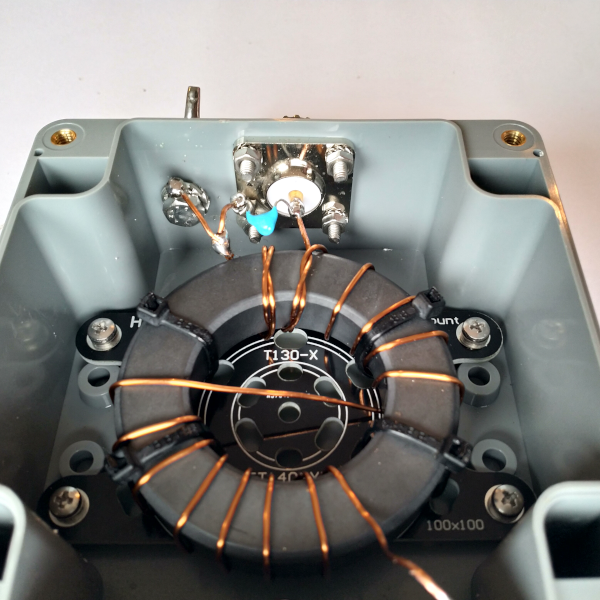
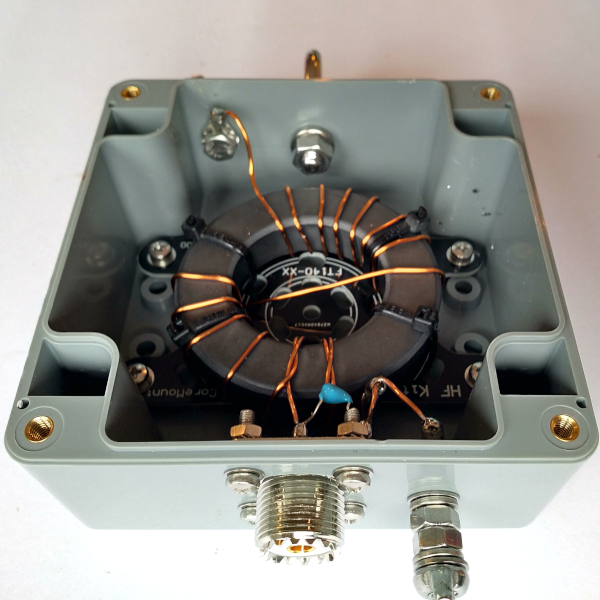
Now cut the wires of the transformer to length and screw the toroidal core into the housing. A capacitator of 100 pF can now be placed over the primary side of the transformer, so we can compensate any (unwanted) secondary capacity. Incidentally, this will mainly be noticeable on the higher bands 15 -12 – 10 meters. If you don’t use it, consider leaving it out. Now connect the primary side of the transformer to the chassis socket and the counter capacitance connection as shown in the picture below. Make sure that the enameled copper wire is completely released from insulation material. You can easily scrape off the insulation with a knife or sandpaper. Make sure to do this properly and carefully, so a good solder connection is established.
After this mirroring of the primary side, connect the secondary side of the transformer to the antenna connection. For this you can use the included toothed spring washers and place them below and above the M5 cable lugs (which means that these are inside the housing and not on the outside). In this way, the bolt will never turn when the connection to the antenna wire is established.
You can test the End Fed antenna impedance transformer by using a resistance of about 2500 Ohm (for example 2K7) on the ground of the coax connector and antenna connection. In this way, the SWR meter should show a standing wave ratio of approximately 1:1.5 or lower. It is important that an induction free resistor is used and that the connecting wires are as short as possible. Usually the SWR meter does show some reflection power with this test. Of course it is also possible to test with a half wavelength of wire.
Applications
It is easy to come up with lots of antenna varieties that you can match with the 1:49 impedance transformer. In theory it’s possible to connect any half wavelength or a multitude of this to the transformer, in order to get a resonant antenna. Here are a few examples: 5 meters of wire is a half wave for a 10 meter band. 10 meters of wire is a half wave length for the 20 meter band and two times a half wave length for the 10 meter band. 20 meters of wire is a half wave length for the 40 meter band, but also full wave for the 20 meter band, double full wave for the 10 meter band and 3 half wave length for the 15 meter band. The advantage of the amateur bands is that the frequency doubles every time. So 3.5 MHz, 7 MHz, 14 MHz, 21MHz etc. This makes it very easy to create a multiband antenna for these bands.
When you apply a coil in the End fed antenna, something interesting happens. The coil forms a high impedance for the higher frequencies, so the last part of the wire will not participate. This last part, including the entire antenna, only participates for the lower frequencies. In case of the 10,20,40 meter End Fed, only the first 10,1 meter of the wire will work on 10 and 20 meter. The entire antenna is 12 meters long mechanically, but forms an electic length of 20 meters for the 40 meter band because of the coil. This means it creates a half wave length for the 40 meter band. The disadvantage of working with a shorter antenna is that you will have a limited bandwith.
10 and 20 meter band

Total length +/- 10 meters.
10, 20 and 40 meter band, with coil

Total length +/- 12 meters
10, (15), 20 and 40 meter band
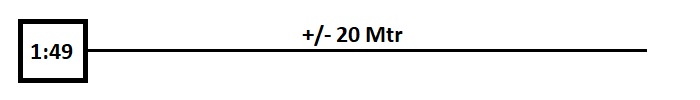
Total length +/- 20 meters
10, (15), 20, 40 and 80 meter band, with coil
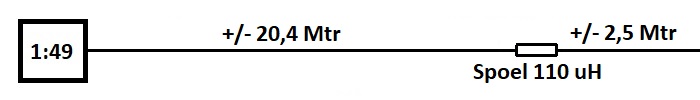
Total Length +/- 23 meters
The coil
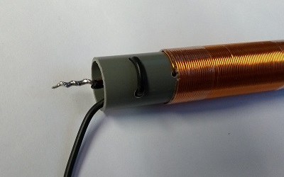
You might use several ways to incorporate the coil into the antenna wire. Below is a visual representation of a way that works properly. To get a 35 uH coil around a 19 mm PVC pipe, one can use 80 windings of 0,75 mm (0,44 mm2) winding wire. For the 110 uH coil one can make 170 windings with 0.5 mm (0.20 mm2) winding wire. For deviating coils or a different diameter of winding wire, the following tool exists. Download link to Mini Ringkern Rechner: Click here!!!
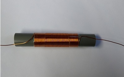
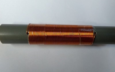
Try to wrap the coil as tight as possible, so there will not be any space left between the windings. Then fix the entire piece with some tape. Continue by drilling two small holes, right next to the coil, where you can stick the ends of the wire in.
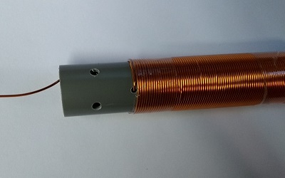
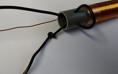
The next step is to drill two more holes as shown in the photo above. These holes will be used to put the wire through, which will be used as the strain relief. Finish this step by tying a knot in the wire and pulling it tight.
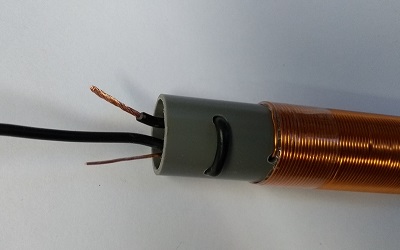
The excess wire can be cut off from the winding wire and the antenna wire. Leave just enough so there will be enough material for soldering. Make sure that the winding wire is completely stripped of the enamel layer. This can easily be done with a sharp knife or some sandpaper. Now solder the wire to the coil and put this into the pipe.
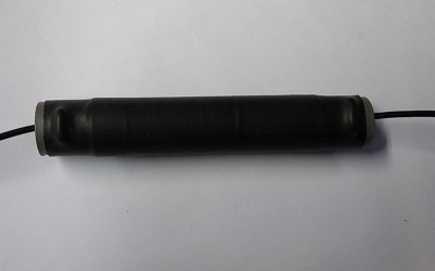
Now apply the heat shrink and heat evenly until the heat shrink fits nicely.
Fine tuning
Place the finished End fed antenna in the desired spot, with some extra wire lenght attached to it The first step is to then tailor the wire for the higher frequencies. This is the piece of wire that is connected directly to the impedance transformer. Keep in mind: it’s possible to cut it off, not to put it back on. So don’t cut too enthousiastically If the higher frequencies show an average and acceptable SWR, you can start to tailor the part of wire behind the coil for the lowest band.
Interested?? Click here to visit the webshop for more information and orders
Need counter poise capacity?
Many discussions on the use of counter capacity in End fed antennas exist on the internet and in literature. Interested to read more about it? The following article elaborates on this topic.