

Antenna impedance theory and practice
Here I would like to try to explain in detail the theory and practice of antenna impedance. A number of popular variants are discussed with their characteristic antenna impedance.
I start at the beginning and finish perhaps somewhat complex.
An antenna is an instrument that converts alternating voltage electrical signals into electromagnetic fields. For receipt, of course, this is in reverse.
Ideal antenna?
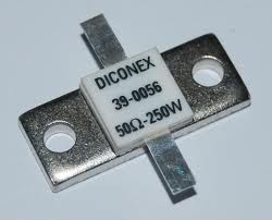
Almost all amateur tranceivers are nowadays equipped with a coaxial connection with an impedance of 50 Ohm. The most ideal antenna for the average amateur radio is therefore a 50 Ohm resistor. Such a resistor doesn’t radiate of course, but the transceiver can handle this impedance well.
Impedance versus voltage and current
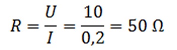
Why was a “standard impedance” chosen? This has been done so that each manufacturer can configure his output stage so that the required power can be supplied at a load of 50 Ohm. In the formula on the picture you can see that a power of 2 Watt is being generated.
After all, 0.2A x 10V = 2Watt.
Suppose that 50 Watt has to be supplied then it is known that the generated voltage must be 50 Volt, the current that then runs is 1 Ampere.
After all, the impedance is 50 Ohm. R = U / I –> 50 Ohm = 50 Volt / 1 Amp.
The power: P = U x I –> 50 Watt = 50 Volt x 1 Ampere
The manufacturer can use this information to determine the correct semiconductors for the output stage. Each type of semiconductor is subject to certain specifications. Think of maximum voltage and current.
In the above examples a purely ohmic load is assumed. This means that the voltage and current are in phase. So there is no phase difference in voltage and current. With an inductive or capacitive load, there is a phase shift. If this sounds somewhat incomprehensible, don’t panic… I’ll come back to this later. For now, at least assume that a resonant antenna always forms an ohmic load for the tranceiver.
Single resonant antennas
Here are some examples of resonant antennas. An antenna that is resonant radiates in principle, this does not mean that the antenna also has the right antenna impedance. Take a look at the examples below. In many cases the antenna has a different impedance. Dipole antennas and BalUn construction description
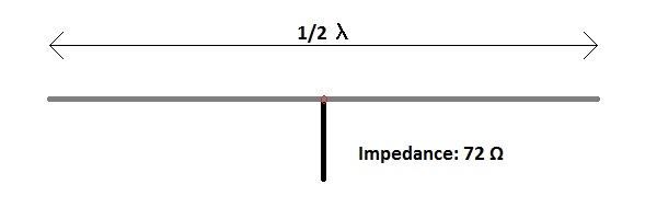
Open half wave dipole antenna
The dipole antenna is one of the best known antennas. This antenna has a theoretical antenna impedance of 72 Ohm. In practice, the antenna often hangs too close to the ground surface, causing the impedance to drop towards the 50 Ohm. In many cases, therefore, an adjustment is not necessary. The ideal height is half the wavelength for which the antenna is suitable.
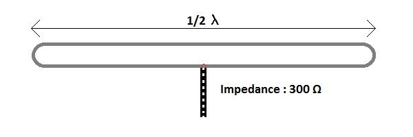
Closed half wave dipole antenna
A closed dipole was often used in the past because a balanced 300 Ohm feed line was chosen more often. In this case, the antenna is equally suitable for this power supply. A closed dipole can of course still be used, the antenna impedance has to be transformed to 50 ohms.

Open whole wave dipole antenna
A whole wave antenna is rarely powered in the middle, as you can see the impedance is very high. As a result, a huge impedance transformation has to be made.
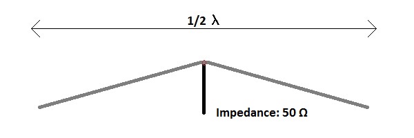
Inverted V dipole antenna
An inverted V antenna is naturally very close to the impedance of 50 Ohm, which makes the antenna very popular with amateurs. Often a high feed point is chosen and the ends are then slightly lowered. In any case, make sure that the ends are a few meters above the ground.
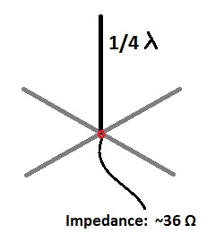
Quadrant wave vertical
A quarter wave vertical can actually be seen as a vertical half wave dipole, with one half standing straight up. The missing half is absorbed by the earth’s surface. This reduces the antenna impedance considerably. If the antenna is placed on the ground, a good earth is extremely important. The type of soil also plays a significant role. If the antenna is placed above the ground, radians of at least a quarter of a wavelength must be placed. One will see that the amount of radians has a big influence on the impedance of the antenna.
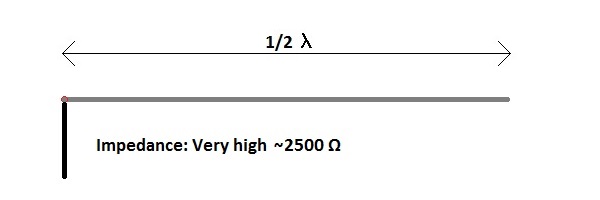
End fed half wave antenna
A terminal powered wire antenna has been very popular lately. This type of antenna has the advantage that it can be powered at the beginning (or end). For many people this is very practical because there is no power cable running through the garden. A disadvantage is the impedance transformation that has to be made. The impedance is very high with this antenna. There are many possibilities to use this type of antenna as a multi-band antenna. I’ll come back to this later.
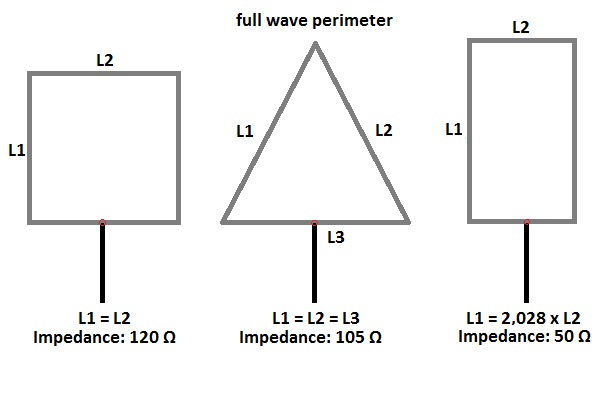
Quad loop antenna
The Quad antenna is in many cases also very interesting. The circumference is a whole wave length. This makes the sides shorter than a dipole. This sometimes makes placement easy. The impedance, as you can see in the picture, strongly depends on the shape. If elements are added, for example to give the antenna more gain in a certain direction, the impedance drops. This makes a square quad antenna with one reflector and two directors about 50 Ohm. The polarization depends on the feed point. This only affects ground wave connections. After reflection in the atmosphere, it is no longer possible to predict the polarisation of the radio waves.
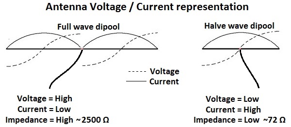
Current / Voltage relationship in the antenna
In the picture above, the relation between current and voltage is given in the antenna. The relationship between voltage and current is actually impedance. From the picture it is clear that the impedance depends on the feed point. It can be seen that a whole wave antenna has a high impedance in the middle as well as at the end. A half wave antenna has a low impedance in the middle (like a half wave dipole) and a high impedance at the ends. Think for example of the end-fed half wave antenna. Conclusion so far. A resonant antenna forms an ohmic load of which the impedance strongly depends on the feed point possition.
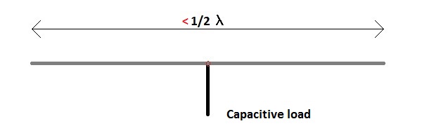
Dipole antenna too short
An antenna is basically resonant if it has a length of half a wavelength or a multiple thereof. All the above antennas are good examples of this. What happens if the antenna is too short for the used frequency? In this case, the antenna behaves capacitively. This can be represented as a resistor with a capacitor in series.

Dipole antenna too long
An antenna that is too long for the working frequency behaves inductively. This can be represented as a resistor and an inductor in series.
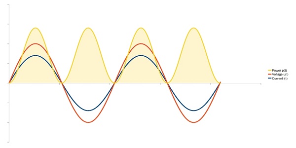
Ohmic load
If the antenna is resonant. So not too short and not too long then Voltage, Current and Power look like this. In this picture you can clearly see that Voltage and Current are in phase. The peaks and troughs of current and voltage occur at the same time.
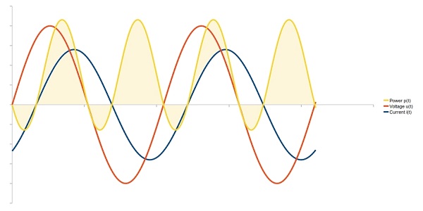
Inductive load (reactance)
If the antenna is not resonant. So the antenna is too short or too long then Voltage, Current and Power look like this. In this picture it is clear to see that Voltage and Current are not in phase. The peaks and troughs of current and voltage do not fall at the same time. In this picture we see that the voltage is ahead of the current. So the current is delirious after the voltage. This takes place with an inductive load (antenna too long). If the antenna is too short, this image will look different. Then the Current is just ahead of the Voltage. So the voltage is dropping. In this picture you can clearly see that something strange also happens to the power.
An antenna tuner can make sure that the load for the tranceiver becomes Ohms again. This is done by switching on coils or capacitors that compensate the reactance of the antenna. Of course, a small part of the power is lost in this tuner.
Antenna impedance multi-band antennas
All antennas mentioned above are in principle only suitable for one frequency. The average broadcasting amateur of course wants to be able to work on several bands. It would therefore also be useful to be able to work with a single antenna in several bands. There are many examples and possibilities to make this happen. I’ll cover some common antennas.
Relationship between supply point and impedance
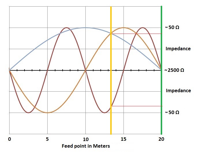
In the picture above, the waves for the 10, 20, 40 meter band are shown in a piece of wire (antenna) 20 meters long. The wire of about 20 meters is resonant for all these bands. Namely a half wavelength for the 40 meter band, a whole wavelength for the 20 meter band and 2 x the wave length on the 10 meter band. Now we have to look for a feed point possition with about the same impedance on all bands. In the picture, the two joint feeding points are marked with a yellow and a green line.
End Fed Antenna
The green line indicates the beginning (or end) of the antenna. At this location, the supply point has a very high antenna impedance for all bands. With an impedance transformer, this feed point impedance can be transformed to the known 50 Ohm for the tranceiver. A well known example of this principle is the end fed antenna. End Fed Antenna Building Description
Or Center Fed / Windom Antenna
The yellow line indicates a feed point on about 1/3 of the wire. At this point a common impedance is also found for these three bands. Keep in mind that the sine in the graph is symmetrical in terms of impedance in the X-axis. (so the sine can be mirrored around the X-axis). The joint impedance at this point is between 200 and 300 Ohm, this depends on the antenna height. So a 1:4 or 1:6 BalUn will have to be applied to get back to the known 50 Ohm.