

Manual 1:2 BalUn 600 Watts for Delta-loop & Quad-loop antennas
This Guide helps you to build the 1:2 BalUn 600 Watts DIY kit step by step. If a delta-loop or quad-loop antenna is powered with a coax cable from the transceiver it is necessary to use a 1:2 BalUn. BalUn means: Balanced to Unbalanced. This allows us to adapt an unbalanced system (coax cable) to a balanced antenna system (delta loop or quad-loop antenna). The characteristic impedance of a delta loop or quad-loop antenna is about 100 Ohm. The transceiver has an impedance of 50 Ohm, so an impedance transformation must also be made.
This 1:2 BalUn uses a symmetrical 1:2 impedance transformer. The 1:2 BalUn 600 Watts is suitable for QRO use. The most important reason to use a good BalUn is to ensure that the coax cable does not become part of the antenna system and therefore radiates as well. This has all sorts of nasty effects, think of: interference, EMI, RFI disrupted radiation pattern of the antenna, restless noise level. This last point is because not only does the coax cable’s shield radiate when you transmit, but the shield also works as a receiving antenna.
Two FT240-43 ferrite toroidal cores are used, one for the BalUn and one for the impedance transformer. The main characteristic of a good BalUn is maximum common mode current reduction and minimal loss of the differential current. There is a lot of information on the Internet and even in literature about making a BalUn, but unfortunately there are also a lot of bad designs that hardly work. This design is one that has proven to work very good!
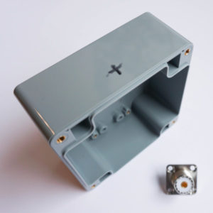
The enclosure
In this step by step manual for the 1:2 BalUn 600 Watts we start by drawing and drilling the hole for the coax connector connection. The diameter of this hole should be 16 mm. This is a large hole and therefore it is easiest to create it with a ‘sheet step drill’. (If you have never heard of that, Google is your friend for looking up what you need)
TIP: Place the hole as high as possible (directional lid) As a result, connecting later is easier. (The center of the hole at 1.5 cm from the edge)
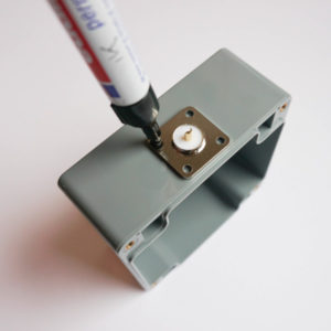
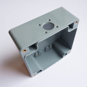
After drilling the 16 mm hole, I placed the chassis part into the hole, to determine the location of the fixing holes. I picked a chassis part where I fix the part with 4 screws, but 2 screws could also work. These holes can be drilled with a 3,5 mm drill.
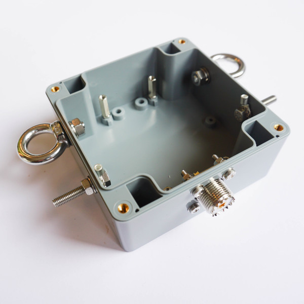
We continue by marking and drilling the holes for the antenna connections and the tensile stools. Especially for longer or permanent antennas it is advisable to use a tensile stool. The hole for the stainless steel eye is drilled with a 6 mm drill and the hole for the antenna connections is drilled with a 5 mm drill. The place where the holes are drilled is to your own liking. After all the holes are drilled all parts can be mounted as shown in the picture below. For the antenna connections above and below the M5 cable lug, use the supplied serrated spring washers (these are both inside the housing and not on the outside), then the bolt will never turn when connecting an antenna wire. Place a flat closing ring on the outside and then an M5 nut.
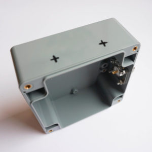
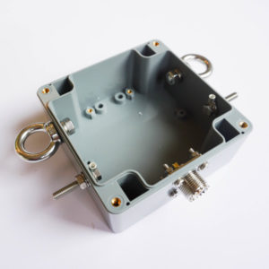
Because two toroidal cores are used for this 1:2 BalUn, the mounting plate has to be raised. Place the M3 spacers as shown in the image below. There are extra nuts around the spacers because otherwise they can damage the housing.
The BalUn
Now it’s time to start the real work, the toroidal cores for the BalUn and the symmetrical impedance transformer. In this kit, the choice was made to use wire with PTFE shielding for the BalUn and 1.5mm copper wire for the impedance transformer. First the BalUn:
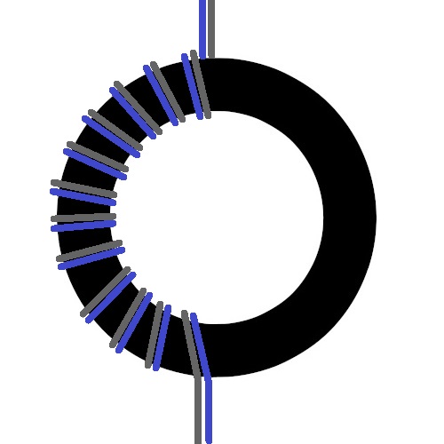
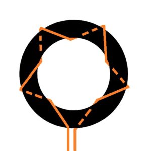
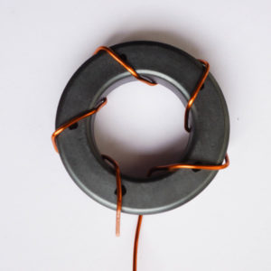
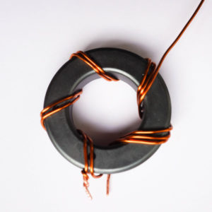
We start by securing two wires with the use of a cable tie. This makes it a lot easier. Keep to the bottom about 7 cm wire length, this is more than sufficient. Then wrap the first 12 windings on half of the toroid as shown in the picture below. Make sure the windings are tightly placed together.
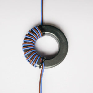
Then wrap 12 windings on the second half. Note that the wires are wrapped exactly as in the example. Do not change colors or wrapping directions. At the bottom of the toroid the two blue wires are next to each other and the black wires on the outside. At the top of the ring core, this is exactly the other way around, there are the black wires next to each other in the middle and the blue wires on the outside. If this is not correct, start again because then something went wrong.
The symmetrical impedance transformer
After wrapping the BalUn it is now time for the impedance transformer.
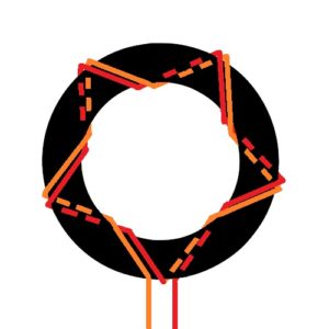
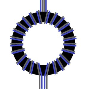
Start winding five windings (yellow in the picture above), divide the windings evenly over the core. Dot with a marker to make an even dividing.
Now wrap another five windings (red) parallel to the first five with the same wire. Cut both wires. (length approximately 1.5 cm) Now scrape the ends of the winding wire bare with a sharp knife or sandpaper. This has to be done properly, otherwise soldering will be difficult.
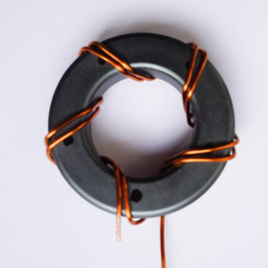
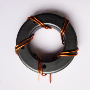
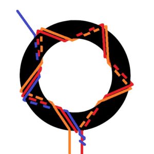
Now make two more pieces of winding wire of approximately 25 cm. Brace or sand the ends of these as well. Connect the end of the piece of wire to the protruding wire of the previously wound winding. Then wrap two more wraps as shown in the images below.
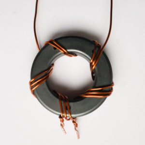
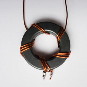
TIP: For a nice flat SWR curve over the entire frequency spectrum, it is important that the three windings run tightly against each other. Use small cable ties every three windings to pull them tightly together. On the picture of the end result you can see these cable ties.
Finishing up
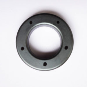
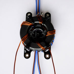
HF Kits has developed a solution for fixating the toroidal cores. With the HF Kits mounting plate it is easy to secure the toroids with a number of cable ties. First attach the toroidal cores to the plate before mounting in the housing.
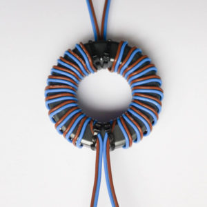
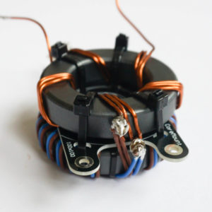
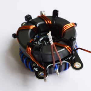
First, lay down the 1:1 BalUn as shown in the photo below left. (Blue wires are at the bottom of the image against each other and the brown wires on the outside) Then put the HF Kits mounting plate on top and then the 1:2 Symmetrical impedance transformer as shown in the picture below. Now connect the two cores with 4 cable ties.
Now solder the BalUn and the impedance transformer together as shown in the picture below. Cut the wires as short as possible but so that they can still be soldered together.
Then connect the primary side of the BalUn (bottom side, where the blue cables are next to each other) to the coax connector. The two blue wires at the center core of the coax connector and the black wires on the chassis part with a cable lug. First cut the blue wires to size as shown in the picture below.
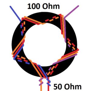
Remove the plastic parts from the three cable lugs so that a solder connection can be made later. Carefully slide the cores into the housing. Guide the blue wires to the coaxial connection. Screw on the mounting plate. Solder the blue wires to the coax connector. Now solder the black wires to the coax chassis socket with the M3 cable lug. The primary side is now connected. Now connect the 100 Ohm side of the impedance transformer to the antenna jacks. Use the supplied M5 cable lug. Also remove the plastic part here.
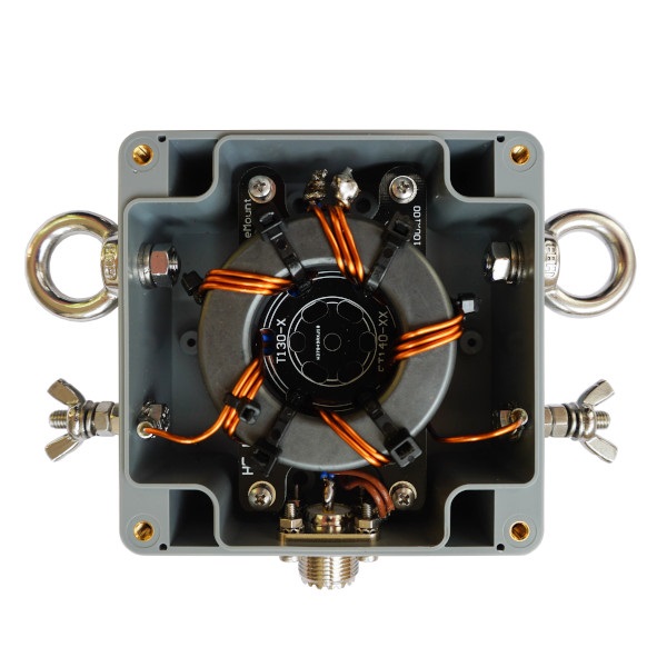
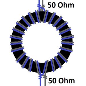
If all goes as planned the whole thing will look like the picture above. Test the 1:2 BalUn by placing a 100 Ohm resistor over the two antenna terminals. Watch out! With this test, use induction free resistors and keep the wires as short as possible. In this way, the SWR meter should show a standing wave ratio of approximately 1:1.5 or lower. Don’t be afraid if at 28 MHz the SWR is against 1:2. This is probably due to the induction of the resistor and the wires. In practice, the SWR is below 1:1.3 over the entire area. Testing with more than one whole wavelength wire (factor 1.06) in the form of a triangle (delta-loop) or square (quad-loop) is of course also possible!
Applications
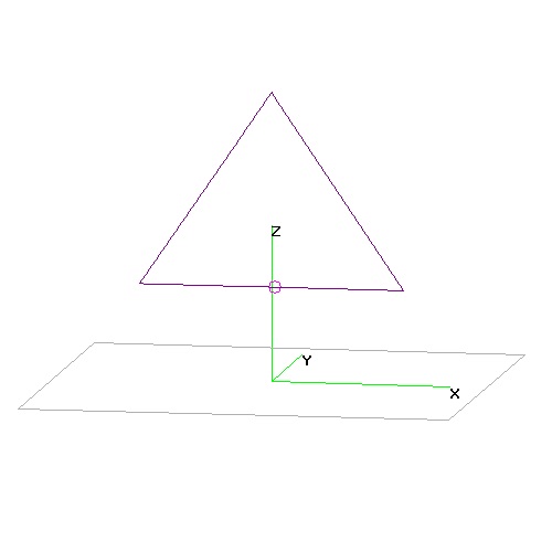
With a 1:2 BalUn you can think of a number of antenna variants. Of course, the antenna must have an impedance of about 100 Ohm at the feed point. It is easy to create a delta-loop or quad-loop antenna. This is a closed antenna with a wire length of more than one wavelength, for the used frequency. The shape is a triangle or square. The radiation angle is determined by changing the position of the feed point and the antenna plane in a different direction.
The Delta loop or Quad-loop antenna is not used as often as compared to other antennas. However, these antennas have many advantages. For example, the antenna is symmetrical and closed so that in many cases the received signal will be quieter compared to asymmetrical or open antennas. Because the antenna is mounted in a triangle or square, less space is needed in many cases. By using a good BalUn, Common mode current are prevented, which also reduces interference from your direct environment. Due to the symmetrical properties of this antenna, no earth or ground capacity is required.
Delta-loop antenna
Make a triangle of more than one whole wavelength long (see table), use the 1:2 BalUn as a feed point to match the impedance of the antenna and prevent common mode currents. Below are four frequently used setups shown. Each setup has its own characteristics.
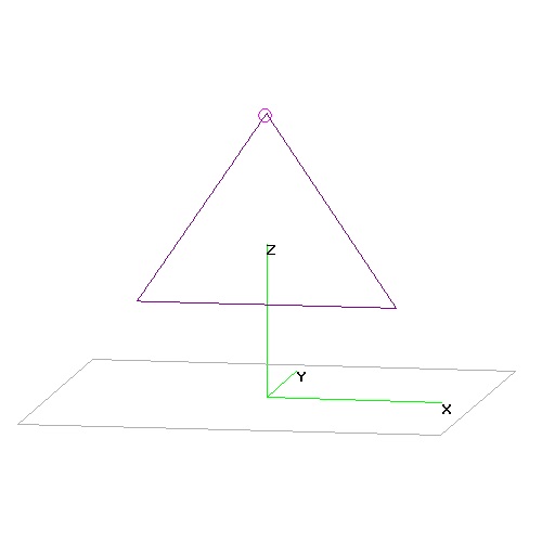
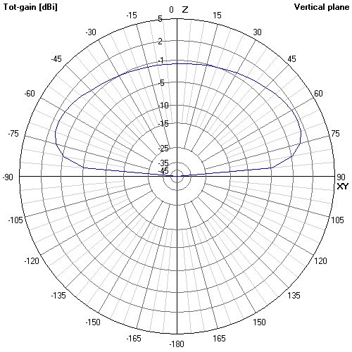
1. The Delta loop antenna is powered from the bottom. This way of feeding is in many cases the easiest in terms of construction. The Antenna mainly radiates between an angle of 45 degrees and straight up. So this antenna is not suitable as a DX antenna, but will mainly perform well locally. If you are looking for a DX antenna go for option 3.
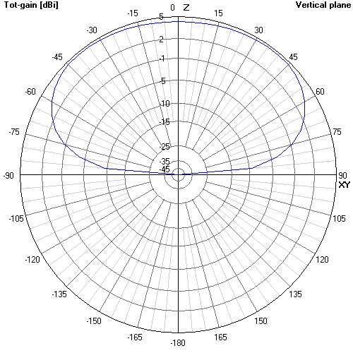
2. The Delta loop antenna shown below is powered at the top. This way of feeding is in many cases not easy in terms of construction and makes no difference to the above antenna in terms of radiation pattern.
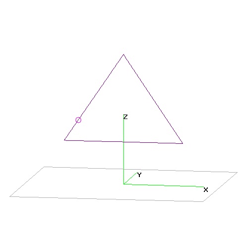
3. The Delta loop antenna below is fed a quarter wavelength from the top. This way of feeding is in many cases quite feasible in terms of construction and has many advantages for DX. The Antenna mainly radiates with an angle of radiation of about 20 degrees and not straight up at all. So this antenna is very suitable as a DX antenna, but will not perform well locally. If you are looking for a DX antenna go for this option.
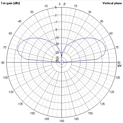
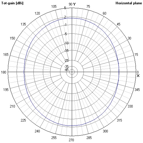
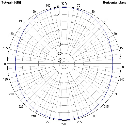
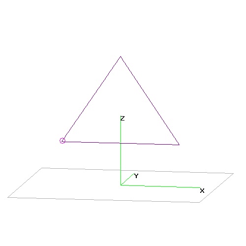
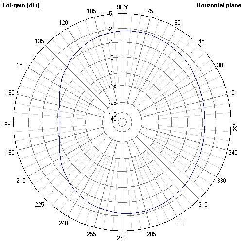
4. The Delta loop antenna below is powered at the corner of the underside. This way of feeding is in many cases very simple in terms of construction. The Antenna radiates in the vertical plane both with a reasonably low beam angle and upwards. You’d say this is a nice all-round antenna. Unfortunately, there is also a disadvantage to this principle. The currents in the antenna do not run symmetrically so that the horizontal plane shows a large dip in the radiation pattern.
The antenna wire length for all variants can be easily looked up in the table below but can also be calculated using the following formula. Always keep the wire longer as the exact length depends on local conditions.
            300
Omtrek = -------- * 1,021
          f (MHz)
Delta loop antenna table
| Band | Frequntie MHz | Golflengte λ | Omtrek Delta-loop | Lengte van één zijde | Afstand voedingspunt vanaf de top |
|---|---|---|---|---|---|
| 160 meter | 1,81 MHz | 165,75 Meter | 169,2 Meter | 56,4 Meter | 42,3 Meter |
| 80 meter | 3,6 MHz | 83,33 Meter | 85,1 Meter | 28,4 Meter | 21,3 Meter |
| 60 meter | 5,35 MHz | 56,07 Meter | 57,3 Meter | 19,1 Meter | 14,3 Meter |
| 40 meter | 7,1 MHz | 42,25 Meter | 43,1 Meter | 14,4 Meter | 10,8 Meter |
| 30 meter | 10,1 MHz | 29,70 Meter | 30,1 Meter | 10,1 Meter | 7,6 Meter |
| 20 meter | 14,15 MHz | 21,20 Meter | 21,6 Meter | 7,2 Meter | 5,4 Meter |
| 17 meter | 18,1 MHz | 16,57 Meter | 16,9 Meter | 5,6 Meter | 4,2 Meter |
| 15 meter | 21,2 MHz | 14,15 Meter | 14,4 Meter | 4,8 Meter | 3,6 Meter |
| 12 meter | 24,95 MHz | 12,02 Meter | 12,3 meter | 4,1 Meter | 3,075 Meter |
| 10 meter | 28,4 MHz | 10,56 Meter | 10,8 Meter | 3,6 Meter | 2,7 Meter |
Quad loop antenna
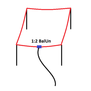
If a square is formed of more than one whole wavelength long together, a quad-loop antenna can be made using a 1:2 BalUn. If the quad-loop antenna is placed horizontally as shown in the picture below, the antenna will mainly radiate upwards. In this setup not suitable as a DX antenna. It’s nice to be able to work locally at 80 metres, for example.
The antenna wire length can easily be looked up in the table below but can also be calculated using the following formula. Always keep the wire longer as the exact length depends on local conditions.
            300
Omtrek = --------  * 1,021
          f (MHz)
Quad-loop antenna table
Always take at least half a meter extra antenna litze than mentioned in the table. This is necessary to be able to make the little loops at the corners and at the BalUn.
| Band | Frequntie MHz | Golflengte λ | Omtrek Quad-loop | Lengte van één zijde |
|---|---|---|---|---|
| 160 meter | 1,81 MHz | 165,75 Meter | 169,2 Meter | 42,3 Meter |
| 80 meter | 3,6 MHz | 83,33 Meter | 85,1 Meter | 21,3 Meter |
| 60 meter | 5,35 MHz | 56,07 Meter | 57,3 Meter | 14,3 Meter |
| 40 meter | 7,1 MHz | 42,25 Meter | 43,1 Meter | 10,8 Meter |
| 30 meter | 10,1 MHz | 29,70 Meter | 30,1 Meter | 7,6 Meter |
| 20 meter | 14,15 MHz | 21,20 Meter | 21,6 Meter | 5,4 Meter |
| 17 meter | 18,1 MHz | 16,57 Meter | 16,9 Meter | 4,2 Meter |
| 15 meter | 21,2 MHz | 14,15 Meter | 14,4 Meter | 3,6 Meter |
| 12 meter | 24,95 MHz | 12,02 Meter | 12,3 meter | 3,075 Meter |
| 10 meter | 28,4 MHz | 10,56 Meter | 10,8 Meter | 2,7 Meter |
Fine tuning
Place the complete Delta-loop or Quad-loop antenna with some extra wire length on the desired spot. Adjust the antenna to the correct length using an antenna analyser or SWR meter. Always remember: you can cut, you cannot add easaly. So don’t cut too excited. Always make sure you cut off both sides equally to keep the antenna symmetrical.
More info
The BalUn and impedance transformer What about exactly?