

Construction manual antenna trap V2
An antenna trap is used in multiband antennas. The antenna trap blocks a certain frequency. This shields part of the antenna for higher frequencies where a shorter antenna is needed. The entire antenna participates for the lower frequencies on which the trap does not block. This can be applied in dipole antennas where each leg of the antenna needs a trap, but also in end-fed antennas where only one trap is needed.
Resonance frequency of the antenna trap
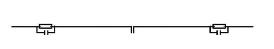
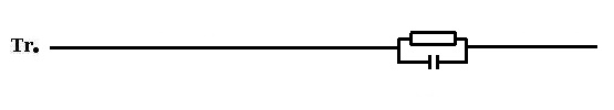
A trap is a parallel circuit of a capacitor and an inductor. The frequency at which the antenna trap has a high resistance (so it blocks) depends on the coil and capacitor. The resonance frequency is determined by the formula below.

I choose to use an easy program that does the math for you.
Download link to Mini Ringker Rechner: Click here!!!
The installation is in German but in the program the language can be changed to English.
First we will determine the value of the coil and capacitor. A rule of thumb is to choose a capacitor value (pF) that corresponds to the band in meters. So for a trap for the 20 meter band, we choose a capacitor value of about 20 pF.
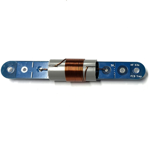
HF Kits use the top and bottom layers of the circuit board as capacitor. Various capacities can be selected by cutting print tracks. In our case, we grind through the white dotted lines on both sides of the circuit board where the number 20 appears.
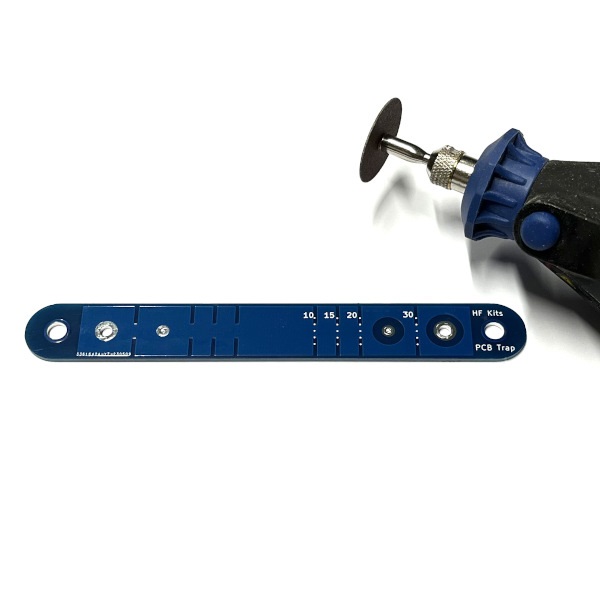
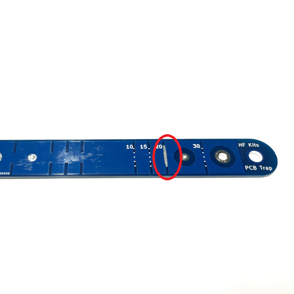
We then get a capacitance of about 24 pF. See the following list of various band choices and corresponding capacity. For the 40 meter band, no PCB traces need to be cut.
- 40 Meter -> +/- 49 pF
- 30 meters -> +/- 37 pF
- 20 meters -> +/- 24 pF
- 15 meters -> +/- 18 pF
- 10 meters -> +/- 12 pF
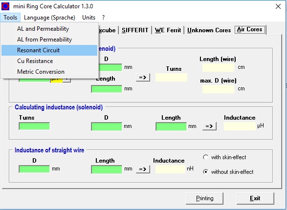
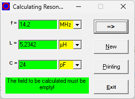
Now that we have determined the capacitor value and it is more or less known, we need to determine the correct value for the coil. For this I use Mini Ringkern Rechner. In the program, choose: Tools –> Resonant Circuit. Enter the value of C and Frequency. I entered 24 pF here as the capacitor value and a frequency of 14.2 MHz. The antenna trap is pretty wideband so the frequency doesn’t come close to a few kilohertz. If I then click on the arrow, the value of the coil is calculated. In this case, 5.23 uH. So we now know that we can start making a trap with a 24 pF capacitor and a 5.23 uH coil.
Determine the number of windings of the coil
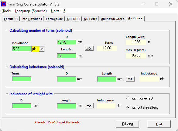
Now return to the main program and choose the tab “Air Cores”. Now enter the inductance of the coil as we calculated earlier in “Resonant Circuit” calculator. Next, we fill in the diameter of the coil, which in our case is 19.75 mm. Then I experimentally determine the length of the coil, I choose about 0.8 mm per winding, so this is a matter of trial and error. I now arrive at 17.6 ( so 18 ) windings with a coil length of 14 mm. We use winding wire of 0.75 mm so with this you would end up with a minimum coil length of (18 x 0.75 mm) 13.5 mm. So there is still some space to slide the coil in and out which is necessary to bring the trap exactly to the right resonance frequency. This will be addressed later when tuning the trap.
Mounting the coil
The base of the coil is in our case a PVC tube in which the PCB fits exactly. Saw in the PVC pipe on two sides, so it forms an easy start and end point of the coil. Solder the enameled copper wire as shown in the picture below. Make sure the insulation is removed properly. This can be done with a sharp knife or sandpaper. Then wrap the coil as shown in the picture below. Solder the other end of the coil to the PCB.
Tuning the antenna trap
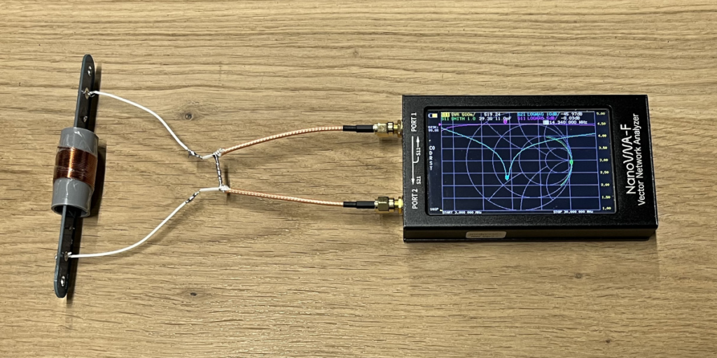
This requires a Nano VNA, grid-dipper or spectrum analyzer. The picture below shows the passage characteristic of the stage being imaged on the NanoVNA. Bringing the windings of the coil closer or further apart changes the resonance frequency. Now set the stage exactly at the desired frequency, 14.2 MHz in this case. A piece of tape around the coil helps keep the windings in position.
Finishing
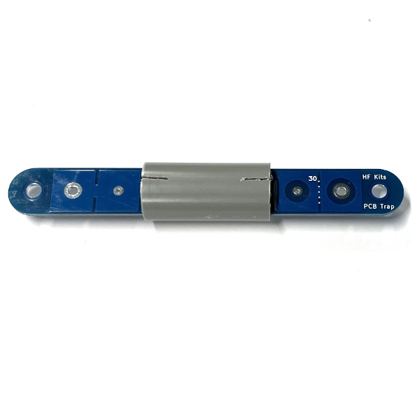
Now that the trap has been brought to the right resonance frequency, it is advisable to fix the coil to prevent it from slipping. I do this with some quick drying plastic spray. PVC glue is also a good alternative. After the coil is fixed, the resonant frequency is checked one more time after which the assembly can be finished. For temporary use, the shrink tubing provided is sufficient. For long-term use, it is necessary to properly protect the trap from moisture. For example, choose plastic-dip or some other method to protect the trap from moisture. Pay attention not to heat the entire trap with the heatshrink tubing, this can deform the PVC and cause the resonance frequency to change.
Mounting the traps in the antenna
There are roughly three ways to mount the trap.
- Insert the antenna wire through the outer hole, then solder to the inner mounting point. This is a suitable way for short antennas that are not set up permanently. This way of mounting is by far the easiest because no loops, cable clips and other attributes are needed. I use this for my short end fed antennas that I use vertically in the field. Choose in this case for: Antenna trap kit, ideal for wire antennas
- Solder the antenna wire into suitable cable eyes M4 or M5 and finish with a piece of heat shrink tubing. Secure the cable lug to the outer fixing holes of the trap using M4 x 10 mm stainless steel bolts. This is a suitable way for medium sized antennas.
- By far the most solid way of mounting is as follows: Make a loop of wire through the outer mounting hole of the trap by means of a stainless steel cable clamp. Use stainless steel cable thimble to prevent the wire from being damaged (missing on the picture below). Solder the antenna to a suitable wire eye (M4) and finish with a piece of heat shrink tubing. Secure the cable lug to the inner fixing hole of the trap using a stainless steel M4 x 10 mm bolt. In this case, please choose: Antenna Trap Kit including cable lug and cable clamps

Example 1: multiband dipole antenna for the 10 and 20 meter band using antenna traps
Start by making two traps that are resonant at the highest frequency. That’s the 10 meter band in this example. If you make the trap’s so that the resonance frequency is at 28.6 MHz, then signals of this frequency will be blocked. Now start making a standard dipole antenna for the 10 meter band. So a feed point (preferably a 1:1 BalUn) and two pieces of antenna wire of about 2.5 meters ( 300 / 28.5 * 0.95 / 4 = 2.5 mtr). Start with a bit more length (2.8 meters) so you can still cut something. Once you have the antenna in resonance for the 10 meter band, the traps can be placed at either end. Now add the other two pieces of antenna wire for the 20 meter section. In our example also about 2.5 meters per side. Now cut the two ends to length so that the antenna is in resonance on the 20 meter band. It is also possible to apply this trick a few more times to add a few more bands to the antenna.
Example 2: multiband end-fed antenna for the 40 and 60 meter band using an antenna trap
Start by making one trap resonant at the highest frequency. That’s the 40 meter band in this example. If you make the trap so that the resonance frequency is at 7.1 MHz, then signals of this frequency will be blocked. Now start making a standard end fed antenna for the 40 meter band. So a feedpoint (1:49 impedance transformer) and a piece of antenna wire of about 20 meters ( 300 / 7,1 * 0,95 / 2 = 20 mtr). Start with some more length (21 meters) so there is still something to cut. Once you have the antenna in resonance on the 40 meter band, the trap can be placed at the end. Now add the remaining piece of antenna wire for the 60 meter section. In our example about 7 meters. Now cut the end to length so that the antenna is in resonance on the 60 meter band. It is also possible to apply this trick a few more times. This makes it possible to add more bands.